
Saturday, November 5, 2011


Tuesday, September 27, 2011
Machine safty and Maintinance
 In manufacturing plants, machine operators handle the machines that create products sold to consumers. Machine operators work in every industry and are involved in detecting problems and offering quick fixes to maintain daily operations. By implementing preventive maintenance, machine operators can keep machines functioning properly so there are no equipment shutdowns that halts the production line. Machine operators work with a variety of equipment such as
Friday, August 26, 2011
maching oprations
Milling Machines: 101
Here’s some basics on milling machines courtesy of the Army Correspondence Course Program.
This is a long one, but if you scratch your head when someone says milling machine, this will give you the START to a basic understanding. Print it out and read it on the can. Make sure to click on read more to get to the whole article.

Milling machines were first invented and developed by Eli Whitney to mass produce interchangeable musket parts. Although crude, these machines assisted man in maintaining accuracy and uniformity while duplicating parts that could not be manufactured with the use of a file.
Development and improvements of the milling machine and components continued, which resulted in the manufacturing of heavier arbors and high speed steel and carbide cutters. These components allowed the operator to remove metal faster, and with more accuracy, than previous machines. Variations of milling machines were also developed to perform special milling operations. During this era, computerized machines have been developed to alleviate errors and provide better quality in the finished product.
2. Milling Machines
a. General. The milling machine removes metal with a revolving cutting tool called a milling cutter. With various attachments, milling machines can be used for boring, slotting, circular milling dividing, and drilling. This machine can also be used for cutting keyways, racks and gears and for fluting taps and reamers.
b. Types. Milling machines are basically classified as being horizontal or vertical to indicate the axis of the milling machine spindle. These machines are also classified as knee-type, ram-type, manufacturing or bed-type, and planer-type milling machines. Most machines have self-contained electric drive motors, coolant systems, variable spindle speeds, and power-operated table feeds.
(1) Knee-type Milling Machines. Knee-type milling machines are characterized by a vertical adjustable worktable resting on a saddle supported by a knee. The knee is a massive casting that rides vertically on the milling machine column and can be clamped rigidly to the column in a position where the milling head and the milling machine spindle are properly adjusted vertically for operation.
(a) Floor-mounted Plain Horizontal Milling Machine (figure 1 above).
[1] The floor-mounted plain horizontal milling machine’s column contains the drive motor and, gearing and a fixed-position horizontal milling machine spindle. An adjustable overhead arm, containing one or more arbor supports, projects forward from the top of the column. The arm and arbor supports are used to stabilize long arbors, upon which the milling cutters are fixed. The arbor supports can be moved along the overhead arm to support the arbor wherever support is desired. This support will depend on the location of the milling cutter or cutters on the arbor.
[2] The knee of the machine rides up or down the column on a rigid track. A heavy, vertical positioned screw beneath the knee is used for raising and lowering. The saddle rests upon the knee and supports the worktable. The saddle moves in and out on a dovetail to control the crossfeed of the worktable. The worktable traverses to the right or left upon the saddle, feeding the workpiece past the milling cutter. The table may be manually controlled or power fed.
This is a long one, but if you scratch your head when someone says milling machine, this will give you the START to a basic understanding. Print it out and read it on the can. Make sure to click on read more to get to the whole article.

FIGURE 1. PLAIN MILLING MACHINE-KNEE TYPE.
1. IntroductionMilling machines were first invented and developed by Eli Whitney to mass produce interchangeable musket parts. Although crude, these machines assisted man in maintaining accuracy and uniformity while duplicating parts that could not be manufactured with the use of a file.
Development and improvements of the milling machine and components continued, which resulted in the manufacturing of heavier arbors and high speed steel and carbide cutters. These components allowed the operator to remove metal faster, and with more accuracy, than previous machines. Variations of milling machines were also developed to perform special milling operations. During this era, computerized machines have been developed to alleviate errors and provide better quality in the finished product.
2. Milling Machines
a. General. The milling machine removes metal with a revolving cutting tool called a milling cutter. With various attachments, milling machines can be used for boring, slotting, circular milling dividing, and drilling. This machine can also be used for cutting keyways, racks and gears and for fluting taps and reamers.
b. Types. Milling machines are basically classified as being horizontal or vertical to indicate the axis of the milling machine spindle. These machines are also classified as knee-type, ram-type, manufacturing or bed-type, and planer-type milling machines. Most machines have self-contained electric drive motors, coolant systems, variable spindle speeds, and power-operated table feeds.
(1) Knee-type Milling Machines. Knee-type milling machines are characterized by a vertical adjustable worktable resting on a saddle supported by a knee. The knee is a massive casting that rides vertically on the milling machine column and can be clamped rigidly to the column in a position where the milling head and the milling machine spindle are properly adjusted vertically for operation.
(a) Floor-mounted Plain Horizontal Milling Machine (figure 1 above).
[1] The floor-mounted plain horizontal milling machine’s column contains the drive motor and, gearing and a fixed-position horizontal milling machine spindle. An adjustable overhead arm, containing one or more arbor supports, projects forward from the top of the column. The arm and arbor supports are used to stabilize long arbors, upon which the milling cutters are fixed. The arbor supports can be moved along the overhead arm to support the arbor wherever support is desired. This support will depend on the location of the milling cutter or cutters on the arbor.
[2] The knee of the machine rides up or down the column on a rigid track. A heavy, vertical positioned screw beneath the knee is used for raising and lowering. The saddle rests upon the knee and supports the worktable. The saddle moves in and out on a dovetail to control the crossfeed of the worktable. The worktable traverses to the right or left upon the saddle, feeding the workpiece past the milling cutter. The table may be manually controlled or power fed.
maching oprations
 Lathe machine operations
1) Facing
This is a process of machining the end or face to produce a smooth, flat surface which is square with the axis of the work. Facing is carried out for the following reasons:
i) To square the end surface
ii) To have an accurate surface from which measurement could be taken
iii) To reduce work to the required length
Cutting is carried out at right angle to the axis of the work.
![[Picture: Strange Machine]](https://lh3.googleusercontent.com/blogger_img_proxy/AEn0k_sQFfCMFyvqP7k3BfDVJMVSO87uQgqQCA3PwbZZdsmEuu0f17694zC5XanfNRyFCbe8uuQI1Fnfp0DyBG7UEFJBCWpjaH7Y12rkCu9h5TFLxw8ALOypJYkJMh4LlqZ_DXvOxoIZ61cngnpdNGopGzVyUwv-JKC0mlUy_DNaRC7HA9Cf_6JDplSq_NGMeGA7qaRG8ODuD7uVbLRRtP0=s0-d)
machine4all
Creasing and Cutting Machines are special equipments for creasing and cutting ordinary cardboard, corrugated board, plastic and leather in general, applicable in printing, packing, decoration and plastic industries.
Major Features:
1. High strength due to one piece casting by using top quality materials for machine body.
2. Smooth running, big pressure and low noise are obviously remarked as 4-step helical gear mechanism is adopted.
3. Operational altitude is reasonably arranged.Moving-bed opens toits optimum.
4. Electrical system is designed in conformity with IEC standard.
5. Concentrated lubricating system.
Major Features:
1. High strength due to one piece casting by using top quality materials for machine body.
2. Smooth running, big pressure and low noise are obviously remarked as 4-step helical gear mechanism is adopted.
3. Operational altitude is reasonably arranged.Moving-bed opens toits optimum.
4. Electrical system is designed in conformity with IEC standard.
5. Concentrated lubricating system.
Sunday, August 14, 2011
LATHE MACHINE Working Principle
The lathe is a machine tool which holds the workpiece between two rigid and strong supports called centers or in a chuck or face plate which revolves. The cutting tool is rigidly held and supported in a tool post which is fed against the revolving work. The normal cutting operations are performed with the cutting tool fed either parallel or at right angles to the axis of the work.
The cutting tool may also be fed at an angle relative to the axis of work for machining tapers and angles.

Construction: The main parts of the lathe are the bed, headstock, quick changing gear box, carriage and tailstock.
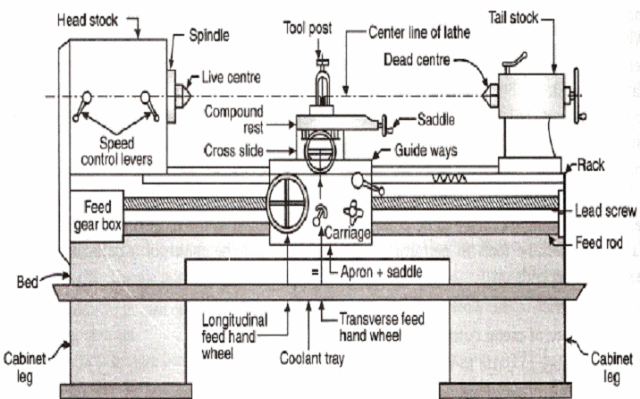
1. Bed: The bed is a heavy, rugged casting in which are mounted the working parts of the lathe. It carries the headstock and tail stock for supporting the workpiece and provides a base for the movement of carriage assembly which carries the tool.
2. Legs: The legs carry the entire load of machine and are firmly secured to floor by foundation bolts.
3. Headstock: The headstock is clamped on the left hand side of the bed and it serves as housing for the driving pulleys, back gears, headstock spindle, live centre and the feed reverse gear. The headstock spindle is a hollow cylindrical shaft that provides a drive from the motor to work holding devices.
assembly of lath machine
Turning machines, typically referred to as lathes, can be found in a variety of sizes and designs. While most lathes are horizontal turning machines, vertical machines are sometimes used, typically for large diameter workpieces. Turning machines can also be classified by the type of control that is offered. A manual lathe requires the operator to control the motion of the cutting tool during the turning operation. Turning machines are also able to be computer controlled, in which case they are referred to as a computer numerical control (CNC) lathe. CNC lathes rotate the workpiece and move the cutting tool based on commands that are preprogrammed and offer very high precision. In this variety of turning machines, the main components that enable the workpiece to be rotated and the cutting tool to be fed into the workpiece remain the same. These components include the following:
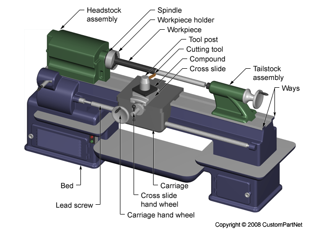
Manual lathe
Bed
- The bed of the turning machine is simply a large base that sits on the ground or a table and supports the other components of the machine.Headstock assembly
- The headstock assembly is the front section of the machine that is attached to the bed. This assembly contains the motor and drive system which powers the spindle. The spindle supports and rotates the workpiece, which is secured in a workpiece holder or fixture, such as a chuck or collet.Tailstock assembly
- The tailstock assembly is the rear section of the machine that is attached to the bed. The purpose of this assembly is to support the other end of the workpiece and allow it to rotate, as it's driven by the spindle. For some turning operations, the workpiece is not supported by the tailstock so that material can be removed from the end.Carriage
- The carriage is a platform that slides alongside the workpiece, allowing the cutting tool to cut away material as it moves. The carriage rests on tracks that lay on the bed, called "ways", and is advanced by a lead screw powered by a motor or hand wheel.Cross slide
- The cross slide is attached to the top of the carriage and allows the tool to move towards or away from the workpiece, changing the depth of cut. As with the carriage, the cross slide is powered by a motor or hand wheel.Compound
- The compound is attached on top of the cross slide and supports the cutting tool. The cutting tool is secured in a tool post which is fixed to the compound. The compound can rotate to alter the angle of the cutting tool relative to the workpiece.Turret
- Some machines include a turret, which can hold multiple cutting tools and rotates the required tool into position to cut the workpiece. The turret also moves along the workpiece, feeding the cutting tool into the material. While most cutting tools are stationary in the turret, live tooling can also be used. Live tooling refers to powered tools, such as mills, drills, reamers, and taps, which rotate and cut the workpiece.
Friday, January 21, 2011
here were two previous versions of Therac machines, each produced by AECL in collaboration with a French company, CGR. Therac 6 and Therac 20 (each named for the MeV they could produce) were based on earlier design from CGR. By the time Therac-25 was released for sale, AECL had 13 years of experience with production of medical linear accelerators. Therac-25 was based on these previous versions. Its main innovations were (1) a "double pass" electron beam so the machine could produce more energy in less space, and (2) the addition of extensive computer control of the machine. This latter innovation allowed AECL to move much of the checking for hazardous conditions into the software.
The Therac-25's ancestors, Therac-20 and Therac-6, had used a minicomputer (a DEC PDP-11) to add some convenience to the standard hardware of a medical linear accelerator. They both could work without computer control. AECL determined to make its new model, Therac-25, a tightly-coupled combination of software and hardware. Therac-25 software was not written from scratch, but was built up from components that were borrowed from the earlier versions of Therac.
The Machine in the RoomTherac-25 is not just a machine, but an installation consisting of the machine, the PDP-11 that controlled the machine, the shielded room the machine sits in, and the monitoring and control station.

The control console and printer etc. are all located outside the heavily shielded treatment room. Thus, when pressing the key to begin the treatment, the operator does not have any direct access to the machine or the patient. All the occurrences in the treatment room must be observed through the TV monitor and the intercom. The intercom works both ways, that is, the patient can hear the operator (if the operator presses a switch) and the operator can hear the patient. The patient, however, cannot see anything outside the treatment room, while the operator can look in using the TV monitor.
Switching Between Modes: The TurntableTherac-25 is a dual mode machine. This means that it can treat the patient with relativelylow energy electron beams or with X-ray beams. In addition, Therac-25 had a "field light" position that allowed a standard light beam to shine in the path of treatment to help the operator in setting up the machine. Thus there were three modes in which the Therac-25 could operate: electron beam and X-ray for treatment, and field light for setup.
Even though they are relatively low energy, the electron beams are too powerful in their raw form to treat the patient. They need to be spread thinly enough to be the right level of energy. To do this, Therac-25 placed what are called scanning magnets in the way of the beam. The spread of the beam (and also it power) could be controlled by the magnetic fields generated by these magnets. Thus for electron beam therapy, the scanning magnets needed to be placed in the path of the beam.
X-ray treatment requires a very high intensity electron beam (25 MeV) to strike a metal foil. The foil then emits X-rays (photons). This X-ray beam is then "flattened" by a device below the foil, and the X-ray beam of an appropriate intensity is then directed to the patient. Thus, X-ray therapy requires the foil and the flattener to be placed in the path of the electron beam.
The final mode of operation for Therac-25 is not a treatment mode at all. It is merely a light that illuminates the field on the surface of the patient’s body that will be treated with one of the treatment beams. This "field light" required placing a mirror in place to guide the light in a path approximating the treatment beam’s path. This allowed accurate setup of the machine before treatment. Thus, for field light setup, the mirror needed to be placed in the path where one of the treatment beams would eventually go.

In order to get each of these three assemblies (scanning magnets or X-ray target or field light mirror) in the right place at the right time, the Therac-25 designer placed them on a
turntable. As the name suggests, this is a rotating assembly that has the items for each mode placed on it. The turntable is rotated to the correct position before the beam is started up. This is a crucial piece of the Therac-25 machine, since incorrect matching of the turntable and the mode of operation (e.g. scanning magnets in place but Electron beam turned on high for X-ray) could produce potentially fatal levels of radiation.
Setup and ActuationThe Therac-25 operator sets up the patient on the table using the field light to target the beam. In doing this, treatment parameters must be entered into the machine directly in the treatment room.
He or she then leaves the room and uses the computer console to confirm the treatment parameters (electron or X-ray mode, intensity, duration, etc.). The parameters initially entered in the treatment room appear on the console and the operator simply presses return to confirm each one.
The computer then makes the appropriate adjustments in the machine (moving the turntable, setting the scanning magnets, setting beam intensity etc.). This takes several seconds to do. If the operator notices an error in the input parameters, he or she can, during the setup, edit the parameters at the console without having to start all over again from inside the treatment room.
When the computer indicates that the setup has been done correctly, the operator presses the actuation switch. The computer turns the beam on and the treatment begins. There are three possible outcomes at this point, and they all depend on sensors on the machine. If the sensors indicate no trouble, the treatment concludes successfully. If the sensors indicate a minor problem, like the beam being slightly out of tune, the computer turns the beam off immediately. The operator can then press a "proceed" key to retry the treatment up to 5 times. If the sensors indicate a more serious malfunction, like the beam being significantly stronger or weaker, the computer turns the beam off immediately and requires the machine to be completely setup from the beginning.
The Therac-25's ancestors, Therac-20 and Therac-6, had used a minicomputer (a DEC PDP-11) to add some convenience to the standard hardware of a medical linear accelerator. They both could work without computer control. AECL determined to make its new model, Therac-25, a tightly-coupled combination of software and hardware. Therac-25 software was not written from scratch, but was built up from components that were borrowed from the earlier versions of Therac.
The Machine in the RoomTherac-25 is not just a machine, but an installation consisting of the machine, the PDP-11 that controlled the machine, the shielded room the machine sits in, and the monitoring and control station.
The control console and printer etc. are all located outside the heavily shielded treatment room. Thus, when pressing the key to begin the treatment, the operator does not have any direct access to the machine or the patient. All the occurrences in the treatment room must be observed through the TV monitor and the intercom. The intercom works both ways, that is, the patient can hear the operator (if the operator presses a switch) and the operator can hear the patient. The patient, however, cannot see anything outside the treatment room, while the operator can look in using the TV monitor.
Switching Between Modes: The TurntableTherac-25 is a dual mode machine. This means that it can treat the patient with relativelylow energy electron beams or with X-ray beams. In addition, Therac-25 had a "field light" position that allowed a standard light beam to shine in the path of treatment to help the operator in setting up the machine. Thus there were three modes in which the Therac-25 could operate: electron beam and X-ray for treatment, and field light for setup.
Even though they are relatively low energy, the electron beams are too powerful in their raw form to treat the patient. They need to be spread thinly enough to be the right level of energy. To do this, Therac-25 placed what are called scanning magnets in the way of the beam. The spread of the beam (and also it power) could be controlled by the magnetic fields generated by these magnets. Thus for electron beam therapy, the scanning magnets needed to be placed in the path of the beam.
X-ray treatment requires a very high intensity electron beam (25 MeV) to strike a metal foil. The foil then emits X-rays (photons). This X-ray beam is then "flattened" by a device below the foil, and the X-ray beam of an appropriate intensity is then directed to the patient. Thus, X-ray therapy requires the foil and the flattener to be placed in the path of the electron beam.
The final mode of operation for Therac-25 is not a treatment mode at all. It is merely a light that illuminates the field on the surface of the patient’s body that will be treated with one of the treatment beams. This "field light" required placing a mirror in place to guide the light in a path approximating the treatment beam’s path. This allowed accurate setup of the machine before treatment. Thus, for field light setup, the mirror needed to be placed in the path where one of the treatment beams would eventually go.
In order to get each of these three assemblies (scanning magnets or X-ray target or field light mirror) in the right place at the right time, the Therac-25 designer placed them on a
turntable. As the name suggests, this is a rotating assembly that has the items for each mode placed on it. The turntable is rotated to the correct position before the beam is started up. This is a crucial piece of the Therac-25 machine, since incorrect matching of the turntable and the mode of operation (e.g. scanning magnets in place but Electron beam turned on high for X-ray) could produce potentially fatal levels of radiation.
Setup and ActuationThe Therac-25 operator sets up the patient on the table using the field light to target the beam. In doing this, treatment parameters must be entered into the machine directly in the treatment room.
He or she then leaves the room and uses the computer console to confirm the treatment parameters (electron or X-ray mode, intensity, duration, etc.). The parameters initially entered in the treatment room appear on the console and the operator simply presses return to confirm each one.
The computer then makes the appropriate adjustments in the machine (moving the turntable, setting the scanning magnets, setting beam intensity etc.). This takes several seconds to do. If the operator notices an error in the input parameters, he or she can, during the setup, edit the parameters at the console without having to start all over again from inside the treatment room.
When the computer indicates that the setup has been done correctly, the operator presses the actuation switch. The computer turns the beam on and the treatment begins. There are three possible outcomes at this point, and they all depend on sensors on the machine. If the sensors indicate no trouble, the treatment concludes successfully. If the sensors indicate a minor problem, like the beam being slightly out of tune, the computer turns the beam off immediately. The operator can then press a "proceed" key to retry the treatment up to 5 times. If the sensors indicate a more serious malfunction, like the beam being significantly stronger or weaker, the computer turns the beam off immediately and requires the machine to be completely setup from the beginning.
Thursday, December 30, 2010
Lathes and Attachments
Levin watchmaker's lathe
 `
`- The basic workhorse in my shop. Most watch parts I make are fabricated on this lathe using one or more of its attachments. This lathe features precision (class 7) preloaded ball bearings in the headstock. Show here is the configuration for turning with the slide rest.


- When drilling small holes in the lathe, better concentricity and less drill breakage can be obtained by turning the drill and the work in opposite directions.. The big brass handle supplies cutting force like a drill press, but the actual feed is controlled by a micrometer knob on the right. This makes it possible to clear out the chips rapidly and resume the cut without "bumping" the bottom of the hole or suddenly breaking through at the end. The dial indicator reads the hole depth directly.The concept of not bumping the hole bottom is important: In steel, any force applied to the drill while not cutting will burnish and harden the surface. This effect is quite pronounced in very tiny holes and was a major problem for the watchmakers in the old days. Modern carbide drills solve this problem, but they are very brittle and won't stand up to any sudden loads. Carbide drills are not (to my knowledge) available is sizes less than 0.004".
Using very small drills in deep holes requires careful attention to centering. The photo on the right shows the micrometer slides for horizontal and vertical adjustment of the spindle. A pair of ground WW collet centers are place in the headstock and drilling spindle. These centers have small round pins rather than points. Under magnification, the micrometers are adjusted to bring these pins into alignment.
This is the ultimate tool for repivoting work or any other precision drilling of small holes. I found this nifty item tossed in a barrel of old fixtures. The feed handle was broken off but it was otherwise undamaged. Levin still sells them for the price of a nice used car.


- This is a pair of steel turns from around the turn of the century. It is illustrated and discussed in Saunier's Watchmakers Handbook. He shows it set up to be a lathe. Boley made a large number of attachments for this "prismatic" lathe bed. I have the set of runners for this tool, but no lathe spindle attachment. Occasionally I use it to finish a staff between dead centers. A part held between dead centers can be adjusted to have practically no radial runout. This insures that the part is concentric. By contrast, a lathe spindle with plain cone bearings must have some radial clearance to carry the oil film. When loaded during the cut, the spindle compresses the oil and can make the part slightly elliptical.
- The view on the right shows the turns up close fitted with a brass driving pulley. The pulley rotates around the fixed center. The pin that sticks out of the pulley engages a spoke on the watch wheel or a small carrier attached to the work.
 In the good old days, this was the principle tool used by the watchmaker for fitting and making round parts. The tool is clamped in the bench vise. The work is held between dead centers and driven with a horsehair bow.
- This 6mm European lathe is shown in its box with accessories. It is designed to be operated with the headstock on the right. (Although it can be switched around, it won't fit in the box that way.) The accessories consist of several drive wheels with pins for turning parts between dead centers, collets, graduated boring cutters and a Jacot drum for clock pivots.Some people make the following distinctions between turning devices:
- Lathe : Has a spindle that rotates in some kind of bearing.
- Turns: Dead centers. A split pulley (ferrule) is attached directly to the part.
- Throw: Dead centers. A pulley runs on one of the centers. A pin extends from the pulley to drive a spoke or carrier (lathe dog) attached to the part. The term throw for this type of drive setup is used mostly by clockmakers e.g. a clockmaker's throw.

- A "wax" lathe is used for turning parts held with a meltable adhesive. This goop, conventionally called wax or lathe cement is actually more like violin rosin. Don't be fooled by the primitive look of this tool. It can support accurate turning that rivals that of most lathes with cone bearings. This technique has been used to make watches for two hundred years. I frequently use lathe cement for holding irregular parts or finishing a balance staff. A glob of cement is inside the hollow spindle which has a recess cut with an accurate female center. The cement is softened with an alcohol lamp and the part is inserted. Now for the magic step: the spindle is revolved while holding a match stick gently against the part. The part will center itself as the cement hardens and (if done properly) the result is extremely concentric. Far better than most collets. I am unable to see any runout (not even vibration) with a Hamilton 0.00005" reading dial gauge.There are lots of recipes for lathe cement. Some folks even use superglue. I mix melted flake shellac with a dab of diamond setter's pitch. The pitch makes the shellac less brittle. I plan to put up a page with recipes for lathe cement. If you have a good one, please send it and you'll get one of the credits! Our work might make Yahoo's bizarre web page of the day...


- A Swiss wax-lathe with attachments from the late 19th century. Show configured as a mandrill on the left and on the right, as a wax lathe. At about this time, the American WW collet lathes were about to displace these attractive, but inconvenient "brass engines".


- The front bearing of the lathe opens to allow rapid replacement of the whole spindle assembly. In the right hand view, the type-metal insert can be seen that supports the wax lathe spindle. When used with the larger mandrill spindle, the insert is removed.

- The lathe on the bench top shown above is a Webster-Whitcomb. This pattern, usually nickel plated, dominated watch lathe design for the next 75 years, displacing both the mandrill and the turns as the most important tool for making and fitting parts.Actually, since the 1940's, the only tools required by the average watch repairer were tweezers, screwdrivers, a cleaning machine and a staking set. The ready availability of interchangeable parts made turning and milling skills unnecessary. Although present on the bench in most jewelry stores, the watch lathe was largely an ornament. Today, with the old factory stocks finally depleted, fine antique watches and clocks must once again be maintained by creating new parts from raw materials.

- This machine is one of the few modernized versions of the watchmakers lathe. Between 1900 and 1970, watchmaker's lathes all looked pretty much like the Webster-Whitcomb shown in the previous section. The F1 is (was?) one of the last designs from the now moribund Boley company, dating from the late 1960's to early 1970s. (Can someone help me date this thing?) One of its unusual features is that the operator may sit at the tailstock end looking into the headstock. A hand rest on the right (behind in this view) supports the right wrist holding the graver on the t-rest, also placed on the right side. The headstock end has a prop that tilts the whole bed toward the operator. In addition, the entire bed rotates along the axis to present a comfortable view. The lathe is ideal for pivoting work in this orientation.The left side (or front as shown here) has a lever that operates an indirect friction drive to a concentric "throw" wheel. The work is held between micro dead centers. A carrier attached to the work is driven by a pin that extends from the throw wheel. This is essentially a modern version of the antique turns discussed above. The dead centers insure absolute concentricity. The friction drive allows the operator to limit the force applied to the work. If the graver catches in the work, the throw wheel will simply stop. Sometimes.
This was my first watch lathe given to me by my wife many years ago. She was quite supportive back before my hobby got completely out of control. To get even, she is now devoted to horsing. It worked.
 When a pivot is broken off, this tool can be used to redrill the arbor so a new one can be pressed into place. Pivots can be as small as 0.004", so this takes some care. To make matters worse, the arbors are commonly hardened. The work is held between centers and driven with a bow as in the turns. The center on the right side is hollow. On the far right side of the case are two small runners that hold the drill. The drill is inserted through the hollow center and pressed against the work while the bow drives it back and forth. The drill is sharpened so it cuts in both directions.

- The Jacot tool is special purpose dead center lathe. It is used to burnish and adjust the size of cone pivots, most frequently on the balance staff. The balance wheel and staff assembly are placed on the tool with one pivot in the female center and the other resting in a groove. The balance is rotated back and forth with a horsehair bow while a burnishing file presses the pivot into the groove. The result is a concentric pivot with a burnished finish. Each of the extra runners has a series of graduated grooves cut on one end. A small gage is included for measuring the pivots.
Atlas Craftsman Metal Lathe Resource CD
I have been working to purchase some basic tools to allow me to perform basic metalworking. One of the first items I purchased was a Craftsman Atlas Metal Turning Lathe Model 101.07403 Catalog number 2079 12x36-inch metal lathe. One of the biggest challenges I faced after I bought the lathe was finding a good source for information about the lathe, its operation, and the various parts and attachments for it. In my search for information I was able to obtain the following documents that I have compiled into a single CD that I am offering to sell to others that may also need this information. The CD is Windows compatible and contains files prepared in PDF format along with a number of photos in JPEG, BMP, and GIF format which should be easily viewable.
 Atlas Press Co. "Manual Of Lathe Operation and Machinists Tables" (276 Pages!) Atlas Press Co. "Manual Of Lathe Operation and Machinists Tables" (276 Pages!)This is a PDF copy of the 1937 "Manual of Lathe Operation" published by the Atlas Press Co. The manual indicates "This manual of Lathe Operation has been prepared to provide fundamental and concrete theory, as well as operating procedure, for students, apprentices and vocational schools". The manual is written around the 12 inch diameter swing Atlas back geared metal lathe but it also covers the six inch, ten inch, and twelve inch models of this lathe that were produced under both the Atlas and Sears "Craftsman" brand names and later under the "Clausing" brand name. The manual contains information on all aspects of machining, including background on lathe construction, shipping, set-up, operation, and methods. This basic design is the same for virtually all manual lathes made up to the present. Newer lathes will have much more complex gearing, although easier to setup, and may be more robust in their construction but the basic operation doesn't change appreciably until you enter CNC lathe operation. Even then knowledge of the basic layout, tool selection, drive speeds, tool feed rates, material setup and support, etc. all are necessary to the safe and productive use of any lathe. Some topics covered in the manual include:
|
South Bend Lathe Works 39th Edition "How to Run a Lathe"(128 Pages) This is an extremely high quality scan and PDF conversion of the 1940 39th Edition of the South Bend Lathe Works book “How to Run a Lathe”. The book is 128 pages in length and the book was carefully disassembled to allow me to get excellent full-page scans of every page in the manual. I. HISTORY AND DEVELOPMENT OF THE LATHE The Tree Lathe; Early French Lathe; Maudslay Lathe; Modern Bench Lathe; Modern Standard Change Gear Lathe; Modern Quick Change Gear Lathe; Tool Room Lathe; Lathe Drives; The Size of Lathe; Types of Lathes for Various Classes of Work; Features the Lathe Should Have II. SETTING UP AND LEVELING THE LATHE Setting Up and Leveling the Lathe; Lacing and Splicing Belts; Shifting Belts; Adjusting Belt Tension; Oiling the Lathe III. OPERATION OF THE LATHE Principal parts of a Lathe; Operation of Headstock; Spindle Speeds; Operation of Carriage and Apron; Operation of Tailstock; Power Carriage Feeds; Notes on Lathe Work IV. LATHE TOOLS AND THEIR APPLICATION Types of Lathe Tools; Position of Lathe Tool; Grinding lathe Tool Cutter Bits; Cutting Power of Lathes. V. HOW TO TAKE ACCURATE MEASUREMENTS Steel Scale; Outside Calipers; Inside Calipers; Hermaphrodite Calipers; Micrometers; Accuracy of a Lathe VI. PLAIN TURNING (WORK BETWEEN CENTERS) Locating the Center; Drilling Center Hole; lathe Dogs; Inserting and Removing lathe Centers; Checking Alignment of Centers; Mounting Work Between Centers; Cutting Speeds; Facing; Turning; Machining to a Shoulder. VII. CHUCK WORK Independent Chuck; Universal Chuck; centering Work in the Chuck; Removing Chuck from Spindle; Hollow Spindle Chuck; Drill Chuck; Draw-in Collet Chuck Head, Hand Wheel and Hand Lever Types. VIII. TAPER TURNING AND BORING Taper Turning with Compound Rest; Taper Boring with Compound Rest; Taper Turning with Tailstock Set Over; Taper Turning with Taper Attachment; Plain and Telescopic Type Taper Attachments; Plain and Telescopic Type taper Attachments; Morse Standard Tapers. IX. DRILLING, REAMING AND TAPPING Using Lathe as a Drill Press; Drill Pad; Crotch Center; Drilling Work Held in Chuck; Reaming; Tapping. X. CUTTING SCREW THREADS Standard Screw Thread Terms; Standard Change Gear Equipment; Quick Change Gear Equipment; Screw Thread Tables; Tools for Cutting Screw Threads; Use of Compound Rest; Thread Cutting Stop; Cutting Threads; Thread Dial; Screw Thread Forms; Metric Screw Threads. XI. SPECIAL CLASSES OF WORK Knurling; Face Plate Work; Filing and polishing; Lapping; Machining Work on a Mandrel; Spring Winding; coil Winding; Boring on lathe Carriage; Use of center Rest; use of Follower Rest; Manufacturing Operations; Milling in the Lathe, etc. |
 Parts List for Craftsman 12-inch Metal Turning Lathe: This is a 300DPI Scanned copy of an original Craftsman Parts list that I converted to PDF. The parts list that I have covers the following Atlas / Craftsman metal lathes:
| ||||||||||||||||||||
 Operating Instructions and Parts List for Craftsman Six-Inch Turning Lathe Model Number 101.21400Eight page PDF copy of the original manual for the 101.21400 Sears Atlas Lathe with description, operation and controls, adjustments, cutting speeds, reading the gear chard, mounting the work; cutting tool bits, indexing, threading, lubrication, and several pages of detailed parts diagrams with parts lists! Operating Instructions and Parts List for Craftsman Six-Inch Turning Lathe Model Number 101.21400Eight page PDF copy of the original manual for the 101.21400 Sears Atlas Lathe with description, operation and controls, adjustments, cutting speeds, reading the gear chard, mounting the work; cutting tool bits, indexing, threading, lubrication, and several pages of detailed parts diagrams with parts lists! | ||||||||||||||||||||
 Sears Craftsman Owners Manual for Model Number 101.28980 and Model 101.28990 Metal LatheTwenty Four page PDF copy of the original manual for the 101.28980 and 101.28990 12-inch metal turning lathe made by Atlas Lathe works for Sears and sold under the Craftsman name. Includes sections on assembly, installation, operation and repair parts. Following is a list of topics from the table of contents: Sears Craftsman Owners Manual for Model Number 101.28980 and Model 101.28990 Metal LatheTwenty Four page PDF copy of the original manual for the 101.28980 and 101.28990 12-inch metal turning lathe made by Atlas Lathe works for Sears and sold under the Craftsman name. Includes sections on assembly, installation, operation and repair parts. Following is a list of topics from the table of contents:Installation (mounting and leveling), Lubrication, Control and Operation (back gear controls, changing spindle speeds, headstock, quick change gear box, carriage, tailstock, sequence of engaging controls, chucks and faceplates) Maintenance and Adjustments (Preventive maintenance, adjusting gibs, adjusting spindle bearings, adjusting compound cross feed cranks, adjusting lead screw safety clutch) PLUS Extensive Parts Index with 9 pages with exploded diagrams of all parts of these lathes with all parts labeled with part number and description. | ||||||||||||||||||||
 Operating Instructions and Parts List for Craftsman Lathe Model Number 101.21270 Operating Instructions and Parts List for Craftsman Lathe Model Number 101.21270Six page PDF copy of the original manual for the 101.21270 Sears Atlas Lathe. Includes complete diagram with parts list, threading chart, and full operating instructions. Some of the operating instructions include: Leveling, lubricating, adjusting the compound slide, carriage adjustments, headstock and tail stock adjustments, motor requirements, cutting speeds, back gear operation, tool bits, chucks, threading gears, etc. | ||||||||||||||||||||
 Operating Instructions and Parts List for Craftsman Lathe Model Number 109.20630 from Nov 1945Seven page PDF copy of the original manual for the 109.20630 Craftsman Lathe with adjustment information including leveling, lubrication; motor requirements; speeds; back gears; RPM calculation; Setting work; Use of Chucks; Thread gears; Setting up Threading Gears; Cutting a Thread; Parts Diagrams and a Threading Chart! Operating Instructions and Parts List for Craftsman Lathe Model Number 109.20630 from Nov 1945Seven page PDF copy of the original manual for the 109.20630 Craftsman Lathe with adjustment information including leveling, lubrication; motor requirements; speeds; back gears; RPM calculation; Setting work; Use of Chucks; Thread gears; Setting up Threading Gears; Cutting a Thread; Parts Diagrams and a Threading Chart! | ||||||||||||||||||||
 Instructions and Parts - Atlas - Clausing Corporation No. 618 6" Atlas Back Geared Screw Cutting Lathe AND No. 12A, 16A Armature Lathe, July 1976 Instructions and Parts - Atlas - Clausing Corporation No. 618 6" Atlas Back Geared Screw Cutting Lathe AND No. 12A, 16A Armature Lathe, July 1976Fifteen page PDF copy of the original manual for the 618, 12A, and 16A Atlas metal lathes which include instructions for mounting the lathe, countershaft, and motor. Includes extensive parts diagrams and parts lists, lubrication charts, speed charts and information on setting lathe speed, and wiring information. | ||||||||||||||||||||
 Instructions and Parts - Atlas Press Company No. 618 6" Atlas Back Geared Screw Cutting Lathe AND No. 12A, 16A Armature Lathe, July 1972 Instructions and Parts - Atlas Press Company No. 618 6" Atlas Back Geared Screw Cutting Lathe AND No. 12A, 16A Armature Lathe, July 1972Fifteen page PDF copy of the original manual for the 618, 12A, and 16A Atlas metal lathes which include instructions for mounting the lathe, countershaft, and motor. Includes extensive parts diagrams and parts lists, lubrication charts, speed charts and information on setting lathe speed, and wiring information. NOTE: This is essentially the same manual as above but both are included in case one manual may show something better then the other! | ||||||||||||||||||||
 Operating Instructions and Parts List for Craftsman Six-Inch Metal Cutting Bench Lathe Model Number 101-07301 Operating Instructions and Parts List for Craftsman Six-Inch Metal Cutting Bench Lathe Model Number 101-07301Five page PDF copy of the original manual for the 101-07301 Craftsman Lathe sold by Sears, Roebuck and Company. Manual includes: Description, Operation and Controls overview, Adjustments, Selecting and setting proper cutting speeds, reading the threading chart, mounting work in the lathe, cutting tool bits, setting the tool to the work, indexing the lathe, threading, using the threading dial, lubrication of the lathe, and complete parts diagram and parts list. | ||||||||||||||||||||
 Atlas Lathe Accessories Catalog (21 Pages): The CD includes a 1996 Atlas lathe parts catalog that includes 21 pages with descriptions, catalog numbers, and photos of accessories and attachments for the Atlas Lathe. The manual includes attachments for 6, 10, and 12-inch lathes. Note: This is actually a scanned photocopy of the original accessory catalog but it is still a useful item to have when you own one of these lathes! | ||||||||||||||||||||
 Atlas Lathe Accessories Catalog (14 Pages): The CD includes a 1937 Atlas lathe parts catalog that includes 14 pages with descriptions, catalog numbers, and photos of accessories and attachments for the Atlas Lathe. The manual includes attachments for 6, 9, and 10-inch lathes. Note: This is actually a scanned photocopy of the original accessory catalog but it is still a useful item to have when you own one of these lathes! | ||||||||||||||||||||
 Atlas Instructions for No. 760 Taper Attachment One page instruction page with info on how to attach and use the Number 760 Taper Attachment . Document also includes a diagram and parts list! | ||||||||||||||||||||
Atlas Lathe Oil Charts: The oil chart is a huge image of the Atlas lathe that could be printed to form a poster for your shop. This image shows all of the key locations that need to be oiled on the 12-inch Atlas Metal lathe. The CD also included oil charts for the various six-inch atlas lathes as well. Atlas Lathe Threading Charts: The Threading Charts include information and settings used with the Atlas Lathe to obtain various threading combinations when threading metal with the Atlas lathe. There are several resolutions of these charts included and they could be printed large enough to make a poster for your work shop if you wanted. The threading charts include the huge charts for the 10 and 12-inch lathes and smaller charts for 6-inch lathes! Old Sears Catalog Pages:I have managed to compile a small collection of Craftsman Tool Catalogs that includes Metal Lathes including 1941, 1944, 1948, 1951, 1953, and 1966. These catalogs are not specific to the Atlas/Craftsman lathe but do show various metal lathes and the later catalogs do included accessories for the 101 Atlas models. Atlas Technical Bulletins: The CD includes Atlas Technical bulletins on the following topics. These bulletins have been converted to user friendly PDF format.
| ||||||||||||||||||||
| ||||||||||||||||||||
| And More... The CD also has a folder that contains photos of various Atlas Craftsman lathes and lathe accessories. I have compiled these photos for myself to have images to refer to while working on my own lathe and I figure that if I have found them useful, you may find them useful too! |

 .
.MAJOR PARTS OF LATHE MACHINE

Belt Tensioning Animation

Motor belt tensioning animation. Taig Lathe manual.
Motor belt tensioning animation. Taig Lathe manual.
Caution: Only use a motor that is either non-thermally protected or has a thermal overload circuit that requires manual reset.
If the motor automatically shuts down due to excessive heat, it then has the potential (upon cooling) to
unexpectedly start-up again while you are touching/changing sharp end mills, saw blades, pulleys or other rotating parts.
If the motor automatically shuts down due to excessive heat, it then has the potential (upon cooling) to
unexpectedly start-up again while you are touching/changing sharp end mills, saw blades, pulleys or other rotating parts.
Sealed, GE H120, ¼ hp, continuous duty, 1725 RPM, split-phase, ball bearing motor,
mounted onto a plate, in-turn held by a large, galvanized door hinge.
Generally, these hinges are loose so it was drilled out and a close-fitting bolt with nut was installed.
mounted onto a plate, in-turn held by a large, galvanized door hinge.
Generally, these hinges are loose so it was drilled out and a close-fitting bolt with nut was installed.

The motor is externally cooled by a fan. Note the height-adjustable rubber stop. This stop allows belt tension
to be set for optimal performance i.e., good traction, minimized vibration & compensation for any minor belt
stretching. It uses a ¼ -20 bolt passing through the work surface & then screws into a flush nut on a small block
of pressure-treated wood. The hard rubber stop has washers on both sides to increase rigidity & a star lock
washer is used under the nut. I enlarged the clearance hole & installed shims on the wooden block. The adjustment
screw is set at an angle perpendicular to the motor mounting plate bottom. The entire rubber stop face is in contact
with the motor mounting plate. There is a spacer plate under the hinge. The power cord is protected from
abrasion that could occur from repeatedly pivoting the motor over time.
to be set for optimal performance i.e., good traction, minimized vibration & compensation for any minor belt
stretching. It uses a ¼ -20 bolt passing through the work surface & then screws into a flush nut on a small block
of pressure-treated wood. The hard rubber stop has washers on both sides to increase rigidity & a star lock
washer is used under the nut. I enlarged the clearance hole & installed shims on the wooden block. The adjustment
screw is set at an angle perpendicular to the motor mounting plate bottom. The entire rubber stop face is in contact
with the motor mounting plate. There is a spacer plate under the hinge. The power cord is protected from
abrasion that could occur from repeatedly pivoting the motor over time.

The sealed motor is impervious to metal debris. ¼ hp is considered by Taig to be the maximum size.
By comparison, this ¼ hp motor is 50% stronger than a 1/6 hp motor & 250% stronger than a 1/10 hp motor.
Mounted to the left (CCW rotation) provides additional work space.
By comparison, this ¼ hp motor is 50% stronger than a 1/6 hp motor & 250% stronger than a 1/10 hp motor.
Mounted to the left (CCW rotation) provides additional work space.

The relatively high motor weight (~13 lbs.) & low belt angle give good tension for turning small parts. The motor
is solid mounted, not in a rubber bushing which causes too much wobble under high torque. This setup also
works well when using the spindle riser block. The ON/OFF switch is a standard, 20A, wall switch mounted in
an outdoor metal switchbox with a stainless steel cover plate. I have the switchbox mounted high on the bench
leg making it difficult to bump it ON (switch down) but if I do accidentally bump it with my knee, it turns the motor
OFF (switch up). Make sure to properly ground the circuit.
is solid mounted, not in a rubber bushing which causes too much wobble under high torque. This setup also
works well when using the spindle riser block. The ON/OFF switch is a standard, 20A, wall switch mounted in
an outdoor metal switchbox with a stainless steel cover plate. I have the switchbox mounted high on the bench
leg making it difficult to bump it ON (switch down) but if I do accidentally bump it with my knee, it turns the motor
OFF (switch up). Make sure to properly ground the circuit.
For low belt tension, the motor plate rests on its stop. Higher belt tension places the plate about one or two mm's
above the stop. Vibration against the stop can occur. When I upgraded the mill motor, I noted the high V-belt traction
due to its locking mounting plate arrangement. This suggested the addition of the hold down action clamp.
In order to eliminate vibration & increase belt tension, install a vertical hold down action clamp from Enco.
Mount it at the same angle as the motor mounting plate. It quickly opens & closes using the lever. When closed,
the motor mounting plate is then captured between the upper & lower adjustable rubber-ended stops.
Belt tension can now be increased when turning larger pieces. Runs very smoothly & with high V-belt traction.
above the stop. Vibration against the stop can occur. When I upgraded the mill motor, I noted the high V-belt traction
due to its locking mounting plate arrangement. This suggested the addition of the hold down action clamp.
In order to eliminate vibration & increase belt tension, install a vertical hold down action clamp from Enco.
Mount it at the same angle as the motor mounting plate. It quickly opens & closes using the lever. When closed,
the motor mounting plate is then captured between the upper & lower adjustable rubber-ended stops.
Belt tension can now be increased when turning larger pieces. Runs very smoothly & with high V-belt traction.
Motor Switches
 Under the bench power switch arrangement. Note the (blue) lathe mount reinforcement plate.
(The DC variable-speed motor controller has been removed)
Under the bench power switch arrangement. Note the (blue) lathe mount reinforcement plate.(The DC variable-speed motor controller has been removed)

Motor-reversing switch shown. Switch is down for normal, CCW rotation & up for reverse, CW rotation.
Wiring schematic is on the motor ID plate.
Jackshaft Speed-reduction Pulley

Lathe speed-reduction pulleys are called jackshafts or countershafts. This design is very sturdy & compact.
Added a 3rd, intermediary pulley, yielding a 10:1 motor to spindle reduction producing a low 178 RPM.
The ⅜" thick arm has vertical height & pivot adjustments using a 10-32 thumb knob in a machined slot.
It is mounted onto the extended stepper-motor bracket making an overall strong, rigid arrangement.
 The axle is in a precision reamed ¼" bracket hole & held in place using a 10-32 nylon-tipped setscrew.
Note the rubber bumper (left) that the motor rests against when pivoted forward to change pulleys/belts.

Two, Taig mill belts (12.5cm flat length) & another Taig pulley were used in the modification.
The 305 in-oz lead screw stepper motor is tucked in close & out of the way; everything clears.
This design was also used for the Taig mill speed-reduction pulley modification.

To return to the original configuration, the motor pulley is first removed, the intermediary bracket with the pulley
assembly folded down (or removed), the motor pulley is reinstalled (flipped 180°), & the longer belt, installed.

The knob has since been replaced with a die cast zinc ratcheting locking lever to enable a tighter hold.

One of the 3rd pulley bearings is exposed by pulling the axle out.Two, sealed, deep-groove, radial/thrust ball bearings were used; ¼" ID & ⅝" OD. The Taig pulley is
made to an interference fit tolerance thereby requiring it to be first heated before installing the bearings.
Inside, in between the bearings, on the ¼" SS axle, there is a thin metal tube spacer that contacts the hubs.The steel collar with setscrew also has a small ridge that only contacts the bearing's hub.
 Even though the pulley runs on two sealed bearings, there is a 0.635" unsupported area of axle where the
hole ID narrows from ⅝" to ⅜". Added an oil-impregnated bronze bearing to lend additional support for the
⅜" pulley hole area. The 0.318" diameter ridge (left) allows only the edge to contact the inner bearing hub.

A ¼" collar acts s a spacer & another (third) thrust bearing.

Before the addition of the bronze bearing, a knocking sound was present under heavy belt tension & the RPM
readout in Mach3 (with averaging on) use to vary by one count. Now, the 3rd pulley runs very quietly under
high belt tension & the RPM is rock solid. The bearing has white lithium grease as an additional lubricant.
Subscribe to:
Posts (Atom)