Pages

click here

Thursday, December 30, 2010

Lathes and Attachments

Levin watchmaker's lathe
    `
    The basic workhorse in my shop. Most watch parts I make are fabricated on this lathe using one or more of its attachments. This lathe features precision (class 7) preloaded ball bearings in the headstock. Show here is the configuration for turning with the slide rest.
Micro drilling attachment
     
    When drilling small holes in the lathe, better concentricity and less drill breakage can be obtained by turning the drill and the work in opposite directions.. The big brass handle supplies cutting force like a drill press, but the actual feed is controlled by a micrometer knob on the right. This makes it possible to clear out the chips rapidly and resume the cut without "bumping" the bottom of the hole or suddenly breaking through at the end. The dial indicator reads the hole depth directly.The concept of not bumping the hole bottom is important: In steel, any force applied to the drill while not cutting will burnish and harden the surface. This effect is quite pronounced in very tiny holes and was a major problem for the watchmakers in the old days. Modern carbide drills solve this problem, but they are very brittle and won't stand up to any sudden loads. Carbide drills are not (to my knowledge) available is sizes less than 0.004". Using very small drills in deep holes requires careful attention to centering. The photo on the right shows the micrometer slides for horizontal and vertical adjustment of the spindle. A pair of ground WW collet centers are place in the headstock and drilling spindle. These centers have small round pins rather than points.  Under magnification, the micrometers are adjusted to bring these pins into alignment. This is the ultimate tool for repivoting work or any other precision drilling of small holes. I found this nifty item tossed in a barrel of old fixtures. The feed handle was broken off but it was otherwise undamaged. Levin still sells them for the price of a nice used car.
Boley Turns
 
      
    This is a pair of steel turns from around the turn of the century. It is illustrated and discussed in Saunier's Watchmakers Handbook.  He shows it set up to be a lathe. Boley made a large number of attachments for this "prismatic" lathe bed. I have the set of runners for this tool, but no lathe spindle attachment. Occasionally I use it to finish a staff between dead centers.  A part held between dead centers can be adjusted to have practically no radial runout. This insures that the part is concentric. By contrast, a lathe spindle with plain cone bearings must have some radial clearance to carry the oil film. When loaded during the cut, the spindle compresses the oil and can make the part slightly elliptical.
    The view on the right shows the turns up close fitted with a brass driving pulley. The pulley rotates around the fixed center. The pin that sticks out of the pulley engages a spoke on the watch wheel or a small carrier attached to the work.
Plain steel turns
    In the good old days, this was the principle tool used by the watchmaker for fitting and making round parts. The tool is clamped in the bench vise. The work is held between dead centers and driven with a horsehair bow.
Lorch-Schmidt lathe outfit
     
    This 6mm European lathe is shown in its box with accessories. It is designed to be operated with the headstock on the right. (Although it can be switched around, it won't fit in the box that way.)  The accessories consist of several drive wheels with pins for turning parts between dead centers, collets, graduated boring cutters and a Jacot drum for clock pivots.Some people make the following distinctions between turning devices:
    • Lathe : Has a spindle that rotates in some kind of bearing.
    • Turns: Dead centers. A split pulley (ferrule) is attached directly to the part.
    • Throw: Dead centers. A pulley runs on one of the centers. A pin extends from the pulley to drive a spoke or carrier (lathe dog) attached to the part. The term throw for this type of drive setup is used mostly by clockmakers e.g. a clockmaker's throw.
Bottum wax lathe
    A "wax" lathe is used for turning parts held with a meltable adhesive. This goop, conventionally called wax or lathe cement is actually more like violin rosin. Don't be fooled by the primitive look of this tool. It can support accurate turning that rivals that of most lathes with cone bearings.  This technique has been used to make watches for two hundred years. I frequently use lathe cement for holding irregular parts or finishing a balance staff.  A glob of cement is inside the hollow spindle which has a recess cut with an accurate female center. The cement is softened with an alcohol lamp and the part is inserted. Now for the magic step: the spindle is revolved while holding a match stick gently against the part. The part will center itself as the cement hardens and (if done properly) the result is extremely concentric. Far better than most collets. I am unable to see any runout (not even vibration) with a Hamilton 0.00005" reading dial gauge.There are lots of recipes for lathe cement. Some folks even use superglue. I mix melted flake shellac with a dab of diamond setter's pitch. The pitch makes the shellac less brittle. I plan to put up a page with recipes for lathe cement. If you have a good one, please send it and you'll get one of the credits! Our work might make Yahoo's bizarre web page of the day...
Swiss lathe with mandrill
      
    A Swiss wax-lathe with attachments from the late 19th century. Show configured as a mandrill on the left and on the right, as a wax lathe. At about this time, the American WW collet lathes were about to displace these attractive, but inconvenient "brass engines".
Swiss lathe bearing
      
    The front bearing of the lathe opens to allow rapid replacement of the whole spindle assembly. In the right hand view, the type-metal insert can be seen that supports the wax lathe spindle. When used with the larger mandrill spindle, the insert is removed.
Webster-Whitcomb lathe
    The lathe on the bench top shown above is a Webster-Whitcomb. This pattern, usually nickel plated, dominated watch lathe design for the next 75 years, displacing both the mandrill and the turns as the most important tool for making and fitting parts.Actually, since the 1940's, the only tools required by the average watch repairer were tweezers, screwdrivers, a cleaning machine and a staking set. The ready availability of interchangeable parts made turning and milling skills unnecessary. Although present on the bench in most jewelry stores, the watch lathe was largely an ornament. Today, with the old factory stocks finally depleted, fine antique watches and clocks must once again be maintained by creating new parts from raw materials.
Boley F1 lathe
    This machine is one of the few modernized versions of the watchmakers lathe. Between 1900 and 1970, watchmaker's lathes all looked pretty much like the Webster-Whitcomb shown in the previous section. The F1 is (was?) one of the last designs from the now moribund Boley company, dating from the late 1960's to early 1970s. (Can someone help me date this thing?) One of its unusual features is that the operator may sit at the tailstock end looking into the headstock. A hand rest on the right (behind in this view) supports the right wrist holding the graver on the t-rest, also placed on the right side.  The headstock end has a prop that tilts the whole bed toward the operator. In addition, the entire bed rotates along the axis to present a comfortable view. The lathe is ideal for pivoting work in this orientation.The left side (or front as shown here) has a lever that operates an indirect friction drive to a concentric "throw" wheel. The work is held between micro dead centers. A carrier attached to the work is driven by a pin that extends from the throw wheel. This is essentially a modern version of the antique turns discussed above. The dead centers insure absolute concentricity. The friction drive allows the operator to limit the force applied to the work.  If the graver catches in the work, the throw wheel will simply stop. Sometimes. This was my first watch lathe given to me by my wife many years ago. She was quite supportive back before my hobby got completely out of control. To get even, she is now devoted to horsing. It worked.
Pivot drilling lathe
    When a pivot is broken off, this tool can be used to redrill the arbor so a new one can be pressed into place. Pivots can be as small as 0.004", so this takes some care. To make matters worse, the arbors are commonly hardened. The work is held between centers and driven with a bow as in the turns. The center on the right side is hollow. On the far right side of the case are two small runners that hold the drill.  The drill is inserted through the hollow center and pressed against the work while the bow drives it back and forth. The drill is sharpened so it cuts in both directions.
Jacot tool
     
    The Jacot tool is special purpose dead center lathe. It is used to burnish and adjust the size of cone pivots, most frequently on the balance staff. The balance wheel and staff assembly are placed on the tool with one pivot in the female center and the other resting in a groove. The balance is rotated back and forth with a horsehair bow while a burnishing file presses the pivot into the groove. The result is a concentric pivot with a burnished finish.  Each of the extra runners has  a series of graduated grooves cut on one end. A small gage is included for measuring the pivots.

Atlas Craftsman Metal Lathe Resource CD

I have been working to purchase some basic tools to allow me to perform basic metalworking.  One of the first items I purchased was a Craftsman Atlas Metal Turning Lathe Model 101.07403 Catalog number 2079 12x36-inch metal lathe.  One of the biggest challenges I faced after I bought the lathe was finding a good source for information about the lathe, its operation, and the various parts and attachments for it.  In my search for information I was able to obtain the following documents that I have compiled into a single CD that I am offering to sell to others that may also need this information.  The CD is Windows compatible and contains files prepared in PDF format along with a number of photos in JPEG, BMP, and GIF format which should be easily viewable.
Atlas Press Co. "Manual Of Lathe Operation and Machinists Tables" (276 Pages!)
This is a PDF copy of the 1937 "Manual of Lathe Operation" published by the Atlas Press Co.  The manual indicates "This manual of Lathe Operation has been prepared to provide fundamental and concrete theory, as well as operating procedure, for students, apprentices and vocational schools". 
The manual is written around the 12 inch diameter swing Atlas back geared metal lathe but it also covers the six inch, ten inch, and twelve inch models of this lathe that were produced under both the Atlas and Sears "Craftsman" brand names and later under the "Clausing" brand name.  The manual contains information on all aspects of machining, including background on lathe construction, shipping, set-up, operation, and methods. 
This basic design is the same for virtually all manual lathes made up to the present.   Newer lathes will have much more complex gearing, although easier to setup, and may be more robust in their construction but the basic operation doesn't change appreciably until you enter CNC lathe operation.  Even then knowledge of the basic layout, tool selection, drive speeds, tool feed rates, material setup and support, etc. all are necessary to the safe and productive use of any lathe.
Some topics covered in the manual include:
  • Lathe Set-up
  • Metal cutting methods
  • Cutting tools (types and uses)
  • Machining of various materials
  • Holding work
  • Drilling & Boring
  • Threading & thread cutting
  • Attachments (types & uses)
  • Woodturning
  • Machining Tables
 
South Bend Lathe Works 39th Edition  "How to Run a Lathe"(128 Pages)
This is an extremely high quality scan and PDF conversion of the 1940 39th Edition of the South Bend Lathe Works book “How to Run a Lathe”.  The book is 128 pages in length and the book was carefully disassembled to allow me to get excellent full-page scans of every page in the manual. 
I.      HISTORY AND DEVELOPMENT OF THE LATHE
The Tree Lathe; Early French Lathe; Maudslay Lathe; Modern Bench Lathe; Modern Standard Change Gear Lathe; Modern Quick Change Gear Lathe; Tool Room Lathe; Lathe Drives;  The Size of Lathe; Types of Lathes for Various Classes of Work; Features the Lathe Should Have
II.      SETTING UP AND LEVELING THE LATHE
Setting Up and Leveling the Lathe; Lacing and Splicing Belts; Shifting Belts; Adjusting Belt Tension; Oiling the Lathe
 III.      OPERATION OF THE LATHE
Principal parts of a Lathe; Operation of Headstock; Spindle Speeds; Operation of Carriage and Apron; Operation of Tailstock; Power Carriage Feeds; Notes on Lathe Work
IV.      LATHE TOOLS AND THEIR APPLICATION
Types of Lathe Tools; Position of Lathe Tool; Grinding lathe Tool Cutter Bits; Cutting Power of Lathes.
V.      HOW TO TAKE ACCURATE MEASUREMENTS
Steel Scale; Outside Calipers; Inside Calipers; Hermaphrodite Calipers; Micrometers; Accuracy of a Lathe
VI.      PLAIN TURNING (WORK BETWEEN CENTERS)
Locating the Center; Drilling Center Hole; lathe Dogs; Inserting and Removing lathe Centers; Checking Alignment of Centers; Mounting Work Between Centers; Cutting Speeds; Facing; Turning; Machining to a Shoulder.
VII.       CHUCK WORK
Independent Chuck; Universal Chuck; centering Work in the Chuck; Removing Chuck from Spindle; Hollow Spindle Chuck; Drill Chuck; Draw-in Collet Chuck Head, Hand Wheel and Hand Lever Types.
VIII.      TAPER TURNING AND BORING
Taper Turning with Compound Rest; Taper Boring with Compound Rest; Taper Turning with Tailstock Set Over; Taper Turning with Taper Attachment; Plain and Telescopic Type Taper Attachments; Plain and Telescopic Type taper Attachments; Morse Standard Tapers.
 IX.      DRILLING, REAMING AND TAPPING
Using Lathe as a Drill Press; Drill Pad; Crotch Center; Drilling Work Held in Chuck; Reaming; Tapping.   
X.      CUTTING SCREW THREADS
Standard Screw Thread Terms; Standard Change Gear Equipment; Quick Change Gear Equipment; Screw Thread Tables; Tools for Cutting Screw Threads; Use of Compound Rest; Thread Cutting Stop; Cutting Threads; Thread Dial; Screw Thread Forms; Metric Screw Threads.
XI.      SPECIAL CLASSES OF WORK
Knurling; Face Plate Work; Filing and polishing; Lapping; Machining Work on a Mandrel; Spring Winding; coil Winding; Boring on lathe Carriage; Use of center Rest; use of Follower Rest; Manufacturing Operations; Milling in the Lathe, etc.
 
Parts List for Craftsman 12-inch Metal Turning Lathe:
This is a 300DPI Scanned copy of an original Craftsman Parts list that I converted to PDF.  The parts list that I have covers the following Atlas / Craftsman metal lathes:
Model Number
Catalog Number
101.07403
2073 (18" between centers)
2075 (24" between centers)
2077 (30" between centers)
2078 (36" between centers)
101.27430
2073 (24" between centers)
101.27440
2073 (36" between centers)
 
Operating Instructions and Parts List for Craftsman Six-Inch Turning Lathe Model Number 101.21400Eight page PDF copy of the original manual for the 101.21400 Sears Atlas Lathe with description, operation and controls, adjustments, cutting speeds, reading the gear chard, mounting the work; cutting tool bits, indexing, threading, lubrication, and several pages of detailed parts diagrams with parts lists!
 
Sears Craftsman Owners Manual for Model Number 101.28980 and Model 101.28990 Metal LatheTwenty Four  page PDF copy of the original manual for the 101.28980 and 101.28990 12-inch metal  turning lathe made by Atlas Lathe works for  Sears and sold under the Craftsman name.  Includes sections on assembly, installation, operation and repair parts.  Following is a list of topics from the table of contents:
Installation (mounting and leveling), Lubrication, Control and Operation (back gear controls, changing spindle speeds, headstock, quick change gear box, carriage, tailstock, sequence of engaging controls, chucks and faceplates) Maintenance and Adjustments (Preventive maintenance, adjusting gibs, adjusting spindle bearings, adjusting compound cross feed cranks, adjusting lead screw safety clutch) PLUS Extensive Parts Index with 9 pages with exploded diagrams of all parts of these lathes with all parts labeled with part number and description.
 
Operating Instructions and Parts List for Craftsman Lathe Model Number 101.21270
Six page PDF copy of the original manual for the 101.21270 Sears Atlas Lathe.  Includes complete diagram with parts list, threading chart, and full operating instructions.  Some of the operating instructions include:  Leveling, lubricating, adjusting the compound slide, carriage adjustments, headstock and tail stock adjustments, motor requirements, cutting speeds, back gear operation, tool bits, chucks, threading gears, etc.
 
Operating Instructions and Parts List for Craftsman Lathe Model Number 109.20630 from Nov 1945Seven page PDF copy of the original manual for the 109.20630 Craftsman Lathe with adjustment information including leveling, lubrication; motor requirements; speeds; back gears; RPM calculation; Setting work; Use of Chucks; Thread gears; Setting up Threading Gears; Cutting a Thread; Parts Diagrams and a Threading Chart!

 
Instructions and Parts - Atlas - Clausing Corporation  No. 618 6" Atlas Back Geared Screw Cutting Lathe AND No. 12A, 16A Armature Lathe, July 1976
Fifteen  page PDF copy of the original manual for the 618, 12A, and 16A Atlas metal lathes which include instructions for mounting the lathe, countershaft, and motor.  Includes extensive parts diagrams and parts lists, lubrication charts, speed charts and information on setting lathe speed, and wiring information.
 
Instructions and Parts - Atlas Press Company No. 618 6" Atlas Back Geared Screw Cutting Lathe AND No. 12A, 16A Armature Lathe, July 1972
Fifteen  page PDF copy of the original manual for the 618, 12A, and 16A Atlas metal lathes which include instructions for mounting the lathe, countershaft, and motor.  Includes extensive parts diagrams and parts lists, lubrication charts, speed charts and information on setting lathe speed, and wiring information.
NOTE: This is essentially the same manual as above but both are included in case one manual may show something better then the other!
 
 
Operating Instructions and Parts List for Craftsman Six-Inch Metal Cutting Bench Lathe Model Number 101-07301
Five  page PDF copy of the original manual for the 101-07301 Craftsman Lathe sold by Sears, Roebuck and Company.  Manual includes:  Description, Operation and Controls overview, Adjustments, Selecting and setting proper cutting speeds,  reading the threading chart, mounting work in the lathe, cutting tool bits, setting the tool to the work, indexing the lathe, threading, using the threading dial, lubrication of the lathe, and complete parts diagram and parts list.
 
Atlas Lathe Accessories Catalog (21 Pages):
The CD includes a 1996 Atlas lathe parts catalog that includes 21 pages with descriptions, catalog numbers, and photos of accessories and attachments for the Atlas Lathe.  The manual includes attachments for 6, 10, and 12-inch lathes.  Note:  This is actually a scanned photocopy of the original accessory catalog but it is still a useful item to have when you own one of these lathes!
 
Atlas Lathe Accessories Catalog (14 Pages):
The CD includes a 1937 Atlas lathe parts catalog that includes 14 pages with descriptions, catalog numbers, and photos of accessories and attachments for the Atlas Lathe.  The manual includes attachments for 6, 9, and 10-inch lathes.  Note:  This is actually a scanned photocopy of the original accessory catalog but it is still a useful item to have when you own one of these lathes!
 
Atlas Instructions for No. 760 Taper Attachment
One page instruction page with info on how to attach and use the Number 760 Taper Attachment .  Document also includes a diagram and parts list!
 
Atlas Lathe Oil Charts:
The oil chart is a huge image of the Atlas lathe that could be printed to form a poster for your shop.  This image shows all of the key locations that need to be oiled on the 12-inch Atlas Metal lathe.  The CD also included oil charts for the various six-inch atlas lathes as well.
Atlas Lathe Threading Charts:
The Threading Charts include information and settings used with the Atlas Lathe to obtain various threading combinations when threading metal with the Atlas lathe.  There are several resolutions of these charts included and they could be printed large enough to make a poster for your work shop if you wanted.  The threading charts include the huge charts for the 10 and 12-inch lathes and smaller charts for 6-inch lathes!
Old Sears Catalog Pages:
I have managed to compile a small collection of Craftsman Tool Catalogs that includes Metal Lathes including 1941, 1944, 1948, 1951, 1953, and 1966.  These catalogs are not specific to the Atlas/Craftsman lathe but do show various metal lathes and the later catalogs do included accessories for the 101 Atlas models.
Atlas Technical Bulletins:
The CD includes Atlas Technical bulletins on the following topics.  These bulletins have been converted to user friendly PDF format.
  • 12-Inch Back Gear Instructions
  • Change Gear Modification Instructions
  • Gear Clearance Instructions
  • Instructions for Leveling a Concave or Convex Lathe.
  • Lathe Identification Sheet
  • Leveling Instructions
  • Lubrication Chart for 12-inch Metal Working Lathe.
 
Various Military Lathe and Tool Manuals!
 
TC 9-524:  MANY PAGES Approx 8.2MB in size

Headquarters, Department of the Army. Fundamentals of Machine Tools Training Circular No 9-524This is likely the ULTIMATE Military Machinist Manual!
 
TM 9-3416-239-14&P:  83 Page 1.7MB

TECHNICAL MANUAL OPERATOR’S, ORGANIZATIONAL , DIRECT SUPPORT AND GENERAL SUPPORT MAINTENANCE MANUAL INCLUDING REPAIR PARTS LIST FOR LATHE, ENGINE , FLOOR MOUNTED : 19 - INCH SWING MODELS 17E5 AND 19E7 ( LEBLOND INC.) (NSN 3416-00-252-7094)
 
TM 9-3416-240-14&P:  41 Pages 3.5MB

TECHNICAL MANUAL OPERATOR’S, ORGANIZATIONAL, DIRECT SUPPORT AND GENERAL SUPPORT MAINTENANCE MANUAL INCLUDING REPAIR PARTS LIST FOR LATHE, ENGINE MODEL B-40 (MC ILVANIE MACHINE WORKS) (NSN 3416-00-725-3508)
 
TM 9-3416-244-14&P:  73 Pages 1.8MB

DEPARTMENT OF THE ARMY TECHNICAL MANUAL OPERATOR, ORGANIZATIONAL DIRECT SUPPORT AND GENERAL SUPPORT MAINTENANCE MANUAL INCLUDING REPAIR PARTS LIST FOR LATHE, ENGINE, MOUNTED ON METAL CABINET BASE MODEL 25-451-W/25-651 (3416-00-174-9171)
 
TM 9-3416-223-12:  39 Pages 0.9MB

ORGANIZATIONAL MAINTENANCE MANUAL LATHE, ENGINE, BENCH MOUNTED, SOLID BED TYPE, 10-INCH SWING, NO. 2 MORSE TAPER CENTER, 1-3/8 SPINDLE HOLE, 110-VOLTS, 60-CYCLE, SINGLE PHASE 3/4-HORSEPOWER, W/ARMY DWG NO. 7550151 BENCH (SHELDON MACHINE CO. INC., MODEL XL) (3416-517-0955)
 
TM 9-3416-225-12:  38 Pages 1.0MB

ORGANIZATIONAL MAINTENANCE MANUAL LATHE, ENGINE, BENCH MOUNTED, SOLID BED TYPE, 10 INCH SWING, NO. 2 MORSE TAPER CENTER, 1-3/8 SPINDLE HOLE, 110-VOLTS, 60 CYCLE, SINGLE PHASE 3/4-HORSEPOWER, W/ARMY DWG NO. 7550151 BENCH (STANDARD-MODERN TOOL SERIES 2,000 MODEL 11 INCH) (3416-517-0955)
 
TM 9-3416-230-14&P:  51 Pages 1.0MB

TECHNICAL MANUAL OPERATOR'S, ORGANIZATIONAL, DIRECT SUPPORT AND GENERAL SUPPORT MAINTENANCE MANUAL INCLUDING REPAIR PARTS LIST FOR LATHE, ENGINE TOOLROOM MODEL 1530 (3416-00-517-1051)
 
TM 9-3416-235-14&P:  66 Pages 1.3MB

DEPARTMENT OF THE ARMY TECHNICAL MANUAL OPERATOR, ORGANIZATIONAL, DIRECT SUPPORT AND GENERAL SUPPORT MAINTENANCE MANUAL INCLUDING REPAIR PARTS LIST FOR LATHE, ENGINE: 9-INCH SWING MODEL CL 670Z (SOUTH BEND LATHE) (3416-00-235-0551)
 
TM 9-3418-200-14&P:  43 Pages 1.8MB

TECHNICAL MANUAL OPERATOR’S, ORGANIZATIONAL, DIRECT SUPPORT AND GENERAL SUPPORT MAINTENANCE MANUAL FOR SHAPER, METAL CUTTING, HORIZONTAL MODEL CS100 (SOUTH BEND LATHE) (NSN 3418-00-223-0969)
 
And More...
The CD also has a folder that contains photos of various Atlas Craftsman lathes and lathe accessories.  I have compiled these photos for myself to have images to refer to while working on my own lathe and I figure that if I have found them useful, you may find them useful too!

My Motley Meanderings

It's an old Ross and Alexander 'Randa A' 3 1/2" screwcutting lathe. Actually, that's what it says on the name plate, but I've seen some evidence to suggest that it might really be a Zyto rebadged by R&A to fill a gap in their range.
The first time I restored it was when I bought it in 1991 for £100 from a friend of my Dad's (I was 11 at the time), then it spent the next fourteen years in a leaky garage with only occasional use. I need to modify some motors for my CNC-mill project (extending the shafts to fit rotary encoders), so I decided it was time to move it over to the Nelson workshop (which doesn't leak) and rebuild it for a second time. It's gone from this:
before
to this:
after.
Sadly I don't have any photos from the first restoration. It originally had a totally different drive arrangement with an overhead line shaft and long flat belts. I really don't know how old it is, but I'm pretty sure it's over fifty years old, and it could well be pre-war. The design and build quality weren't all that spectacular to begin with, and it's worn significantly over the decades, but it is still capable of useful work with a little care. I built a small oscillating single cylinder steam engine with it once.
Yes, I know, I took the belt guard off. It was added at my parents' insistence during the first restoration, but it hindered access to some important things and was generally quite inconvenient. Since you have to be constantly vigilant while operating a lathe anyway (big lumps of spinning metal, sharp tools, razor sharp swarf, etc.), the addition of a belt guard doesn't really make it much safer.


MAJOR PARTS OF LATHE MACHINE

Belt Tensioning Animation

Motor belt tensioning animation.  
Taig Lathe manual.
Caution: Only use a motor that is either non-thermally protected or has a thermal overload circuit that requires manual reset.

If the motor automatically shuts down due to excessive heat, it then has the potential (upon cooling) to
unexpectedly start-up again while you are touching/changing sharp end mills, saw blades, pulleys or other rotating parts.
Sealed, GE H120, ¼ hp, continuous duty, 1725 RPM, split-phase, ball bearing motor,
mounted onto a plate, in-turn held by a large, galvanized door hinge.
Generally, these hinges are loose so it was drilled out and a close-fitting bolt with nut was installed.
The motor is externally cooled by a fan. Note the height-adjustable rubber stop. This stop allows belt tension
 to be set for optimal performance i.e., good traction, minimized vibration & compensation for any minor belt
stretching. It uses a ¼ -20 bolt passing through the work surface & then screws into a flush nut on a small block
of pressure-treated wood. The hard rubber stop has washers on both sides to increase rigidity & a star lock
washer is used under the nut. I enlarged the clearance hole & installed shims on the wooden block. The adjustment
 screw is set at an angle perpendicular to the motor mounting plate bottom. The entire rubber stop face is in contact
with the motor mounting plate. There is a spacer plate under the hinge. The power cord is protected from
abrasion that could occur from repeatedly pivoting the motor over time.
The sealed motor is impervious to metal debris. ¼ hp is considered by Taig to be the maximum size.
 By comparisonthis ¼ hp motor is 50% stronger than a 1/6 hp motor & 250% stronger than a 1/10 hp motor.
Mounted to the left (CCW rotation) provides additional work space.
The relatively high motor weight (~13 lbs.) & low belt angle give good tension for turning small parts. The motor
is solid mounted, not in a rubber bushing which causes too much wobble under high torque. This setup also
 works well when using the spindle riser block. The ON/OFF switch is a standard, 20A, wall switch mounted in
 an outdoor metal switchbox with a stainless steel cover plate. I have the switchbox mounted high on the bench
leg making it difficult to bump it ON (switch down) but if I do accidentally bump it with my knee, it turns the motor
OFF (switch up). Make sure to properly ground the circuit.
For low belt tension, the motor plate rests on its stop. Higher belt tension places the plate about one or two mm's
above the stop. Vibration against the stop can occur. When I upgraded the mill motor, I noted the high V-belt traction
 due to its locking mounting plate arrangement. This suggested the addition of the hold down action clamp.
In order to eliminate vibration & increase belt tension, install a vertical hold down action clamp from Enco.
Mount it at the same angle as the motor mounting plate. It quickly opens & closes using the lever. When closed,
the motor mounting plate is then captured between the upper & lower adjustable rubber-ended stops.
Belt tension can now be increased when turning larger pieces. Runs very smoothly & with high V-belt traction.
Motor Switches
Under the bench power switch arrangement. Note the (blue) lathe mount reinforcement plate.
(The DC variable-speed motor controller has been removed)

Motor-reversing switch shown. 
Switch is down for normal, CCW rotation & up for reverse, CW rotation.
Wiring schematic is on the motor ID plate.

Jackshaft Speed-reduction Pulley


Lathe speed-reduction pulleys are called jackshafts or countershafts. This design is very sturdy & compact.
Added a 3rd, intermediary pulley, yielding a 10:1 motor to spindle reduction producing a low 178 RPM.
The ⅜" thick arm has vertical height & pivot adjustments using a 10-32 thumb knob in a machined slot.
It is mounted onto the extended stepper-motor bracket making an overall strong, rigid arrangement.
The axle is in a precision reamed ¼" bracket hole & held in place using a 10-32 nylon-tipped setscrew.
Note the rubber bumper (left) that the motor rests against when pivoted forward to change pulleys/belts.

Two, Taig mill belts (12.5cm flat length) & another Taig pulley were used in the modification.
The 305 in-oz lead screw stepper motor is tucked in close & out of the way; everything clears.
This design was also used for the Taig mill speed-reduction pulley modification.

To return to the original configuration, the motor pulley is first removed, the intermediary bracket with the pulley
assembly folded down (or removed), the motor pulley is reinstalled (flipped 180°), & the longer belt, installed.

The knob has since been replaced with a 
die cast zinc ratcheting locking lever to enable a tighter hold.

One of the 3rd pulley bearings is exposed by pulling the axle out.
Two, sealed, deep-groove, radial/thrust ball bearings were used; ¼" ID & ⅝" OD. The Taig pulley is
made to an interference fit tolerance thereby requiring it to be first heated before installing the bearings.
Inside, in between the bearings, on the ¼" SS axle, there is a thin metal tube spacer that contacts the hubs.
The steel collar with setscrew also has a small ridge that only contacts the bearing's hub.
Even though the pulley runs on two sealed bearings, there is a 0.635" unsupported area of axle where the
hole ID narrows from ⅝" to ⅜". Added an oil-impregnated bronze bearing to lend additional support for the
⅜" pulley hole area. The 0.318" diameter ridge (left) allows only the edge to contact the inner bearing hub.

A ¼" collar acts s a spacer & another (third) thrust bearing.

Before the addition of the bronze bearing, a knocking sound was present under heavy belt tension & the RPM
readout in Mach3 (with averaging on) use to vary by one count. Now, the 3rd pulley runs very quietly under
high belt tension & the RPM is rock solid. The bearing has white lithium grease as an additional lubricant.

Digital Readouts For Your Mill

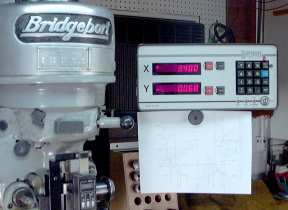
In the last newsletter I discussed the tooling you may want to acquire when you first get your milling machine. One device that can really do a lot to improve productivity and enjoyment of your mill is a Digital Read-Out System.
A digital Read-Out continuously displays the position of the milling table in X and Y coordinates. Some DRO’s are also capable of showing the "Z" position of the knee or quill. The display on the read-out typically uses a red or green LED numbers. The resolution of the display is 0.001" or better. Most displays are capable of 0.0005", or 0.01mm.
Sargon DRO on Bridgeport
Advantages of using a digital read-out
The primary advantage of using a DRO is that the measurements scales, used by the DRO, measure the position of the table directly. Since the measurement is direct, and the lead-screws are not used, effects of back-lash and lead-screw wear do not cause errors in measurement. If you have a mill with worn lead-screws, you may find that it is much cheaper to install a DRO than replace the lead-screws and nuts. The DRO will also allow you to work in metric as easy as imperial. Finally the obvious, no more counting turns and setting dials. Setting zero is as easy as pushing a button.

Types of scales
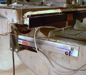
The scale is the device that encodes the position of the table. There are several different technologies used. Examples of types are capacitive, magnetic, rack and pinion with encoder, and optical. The optical are most common. In the optical scales, a long narrow piece of glass has a scale made by coating the glass with a very thin layer of chrome, and photo-etching a series of lines through the chrome. An encoder head, with LED’s and photo-transistors, is moved along the scale. Since glass has a low rate of thermal expansion, this method can give very precise operation.
Scales can vary in thickness as well. Older scales were large and had to be mounted on the front of the table. This could cause problems with the auto-stop feature of the table motor. Many newer scale are scarcely 1/2" thick. This allows mounting behind the table and out of the way. All scale technologies are pretty good, be sue to choose your DRO by looking at the whole system, not just the scales.
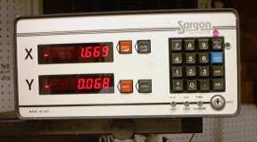
Read-out Displays
There are three levels of read-out devices available from most DRO manufacturers. Pick a readout that fits your needs and budget.
Level-One This is a readout the provides only a single counter for each axis. A reset button is provided for each axis and is used when setting the zero datum point.
Level-Two This type of readout operates in at least two modes, absolute and incremental. This means that there are actually at least two counters provided for each axis. The absolute mode is used to set the primary datum zero. The incremental mode is used to do work based upon a temporary zero at some place on the workpiece. For instance, a bolt circle may have to be drilled centered at some location on a plate. The operator would use absolute mode for finding the center of the bolt circle, then switch to incremental mode, zero the counters, and dial-out the bolt circle based on X-Y coordinates. After the holes are drilled, he places the DRO back into absolute mode and continues to the next machining operation. The absolute coordinates are not affected when the incremental counters are set to zero.
Level-Three This display unit has all the features of the level-two unit, plus, the ability to preset the counters. This simplifies working with large objects where the 0,0 datum cannot be reached to reset the counters. Instead a hole or line intersection is located and the counters are preset to this location. This type of display will also allow the setting of tool diameters for automatically generating the offsets. I prefer to use a calculator for this purpose.
In my opinion, avoid level-one readouts. Repetitive re-zeroing the main counter in the middle of the work can cause accumulated error. Level-two is the way to go for 98% of most of the work done. Buy a level three DRO if you foresee machining large panels.
Using a DRO will change the way you approach a milling machine project. Bolt circles and placing hole patterns at strange angles are now done with the DRO and a calculator, not the rotary table. A few examples of how a DRO is used are shown below.
  1. Zeroing on the corner of a workpiece - Using an edge finder, move up to the edge of the piece until the edge finder touches the piece and bumps to the side. Zero the axis where the movement was made, and raise the quill. Now move ½ of the diameter of the edge finder and reset the counter to zero. I use an edge finder that is 0.200" in diameter, so my movement would be 0.100". Do this for both axes.
  2. Finding the center of a round hole (or object) - Place an edge finder in a collet or chuck. Roughly center the spindle on the hole. Drop the spindle and move the X position until the edge of the hole is detected. Zero the X counter. Move to the other side of the hole using only movement on the X position. Note the reading on the X counter. Divide this reading by two, crank the X hand-wheel until you are at the 1/2 position. Lock the X travel and zero the X counter. Use the same process to find the center on the Y axis. With practice, it should take less that a minute to find the center of most holes. Note that as long as you are finding the center of something, the diameter of the edge detector does no matter, it cancels out.
  3. Drilling a bolt circle - Using the Machinist’s Handbook or a calculator, calculate the X and Y coordinates for each hole based on the center of the pattern being 0,0. Using the absolute mode, move to the center of the bolt circle. Switch to incremental mode and zero X and Y. Now the position of each hole may be found and drilled. Switch back to absolute mode and go on to the next operation on the project.
  4. Machining multiple patterns - such as connector cutouts are simple. When designing the part, don’t bother dimensioning each pattern in detail. Instead show the center of each pattern and one detail with the dimensions referenced to the center of the pattern. When machining, move to the center of each pattern in absolute mode, switch to incremental and zero, then machine the pattern. This saves a lot of time in design, layout, and machining. 
  5. Machining rectangular cutouts and cavities - is simplified by using a DRO. For example, the cutout is 0.820" wide and 0.440" high with 0.062" radius on the corners. This is the size for a 9-pin D computer connector. Use a 0.125" diameter endmill. The X movement would be (0.820 - .125) / 2, or 0.348". The Y movement would be (0.440 - .125) / 2 or 0.158" So while machining the cutout, you would move from 0.348,0.158 to –0.348,0.158 to -0.348,-0.158 to 0.348,-0.158 and back to 0.348,0.158. In actual practice, it is best to make the first pass about 0.03" inside and the final pass at the finish size. The DRO makes this easy because the backlash from the lead screws does not matter. The DRO measures the actual location of the table.
  6. Machining a large plate - when the edge is beyond the reach of your table movements, do the following: Using a surface plate and a height gauge, mark out a set of coordinates on the plate near where the machining will be done. Mount the workpiece on the table making certain that it is square with the table. Using a wiggler or optical finder, locate the spindle directly above the intersection of the two lines. Put the DRO in absolute mode and enter the coordinates using the keyboard on the display unit. If your DRO does not allow presetting of coordinates, zero the X and Y then subtract the offset location from each set of coordinates on the drawing as you locate them on the workpiece.
Using a DRO will change the way you approach machining problems. Working from the center of an object rather than an edge will become commonplace. Instead of detailing the locations every object, step and repeat will make machining faster and easier. Your machining quality and confidence will soar to new heights. And even a forty-year-old mill will produce all the accuracy of a much newer machine.


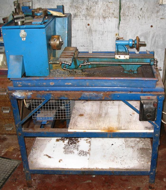
A Lathe Rifling Attachment
By George King

This is the first part of a multi-part article on rifling in the lathe. Download the Drawing Rifling.jpg and print it out before reading this article.
The tool has two parts. Part one, a frame for holding the cutting tool is mounted to the saddle. The cutting tool is rotated by a rack and pinion mechanism, with the pinion gear attached to the rod that holds the cutting tool. Part two, the rack for the pinion gear is bolted to the cross slide.
Most Lathes have two tapped holes on the tail end of the saddle for mounting a follower rest. You will need to drill and tap comparable holes on the head side of the saddle to mount the frames. Use spacers if necessary to insure that the cross slide can clear the frames. I did not show my braces
between the upper sides of the frames because the drawings are already muddled enough.
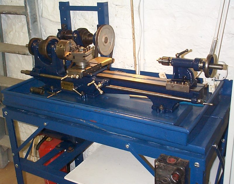
There are two independently rotating assemblies that are only connected by the index pin. The inner assembly consists of a 3/8" rod, the index arm with it's hub, and the rifling rod connector. Set screws secure them together.
The outer assembly consists of the pinion gear, quill shaft and the index plate, all of which are a free fit on the 5/16" rod. A set screw holds the gear hub to the quill shaft, and the index plate is keyed to the latter. The index plate is drilled with holes appropriate for the number of grooves you anticipate rifling.
The rack is mounted on the cross slide in any manner that meshes it with the pinion gear. I used a 12 tooth 24 D.P. spur gear and matching rack.
In use, the cross slide nut is removed and the long taper attachment is connected. It's sine bar is set to produce the desired twist. The rifling rod is screwed into the connector and clamped. After each cut the index pin is moved to the next position. If the head spindle hole is large enough for the barrel blank, it can be held in a clamped chuck. Mine is only 3/4", so I use two center rests jammed to the tail end of the lathe with most of the barrel extending beyond the lathe.
Drawing of Rifiling Jig