
Saturday, November 5, 2011

Tuesday, September 27, 2011
Machine safty and Maintinance
 In manufacturing plants, machine operators handle the machines that create products sold to consumers. Machine operators work in every industry and are involved in detecting problems and offering quick fixes to maintain daily operations. By implementing preventive maintenance, machine operators can keep machines functioning properly so there are no equipment shutdowns that halts the production line. Machine operators work with a variety of equipment such as
Friday, August 26, 2011
maching oprations
Milling Machines: 101
Here’s some basics on milling machines courtesy of the Army Correspondence Course Program.
This is a long one, but if you scratch your head when someone says milling machine, this will give you the START to a basic understanding. Print it out and read it on the can. Make sure to click on read more to get to the whole article.

Milling machines were first invented and developed by Eli Whitney to mass produce interchangeable musket parts. Although crude, these machines assisted man in maintaining accuracy and uniformity while duplicating parts that could not be manufactured with the use of a file.
Development and improvements of the milling machine and components continued, which resulted in the manufacturing of heavier arbors and high speed steel and carbide cutters. These components allowed the operator to remove metal faster, and with more accuracy, than previous machines. Variations of milling machines were also developed to perform special milling operations. During this era, computerized machines have been developed to alleviate errors and provide better quality in the finished product.
2. Milling Machines
a. General. The milling machine removes metal with a revolving cutting tool called a milling cutter. With various attachments, milling machines can be used for boring, slotting, circular milling dividing, and drilling. This machine can also be used for cutting keyways, racks and gears and for fluting taps and reamers.
b. Types. Milling machines are basically classified as being horizontal or vertical to indicate the axis of the milling machine spindle. These machines are also classified as knee-type, ram-type, manufacturing or bed-type, and planer-type milling machines. Most machines have self-contained electric drive motors, coolant systems, variable spindle speeds, and power-operated table feeds.
(1) Knee-type Milling Machines. Knee-type milling machines are characterized by a vertical adjustable worktable resting on a saddle supported by a knee. The knee is a massive casting that rides vertically on the milling machine column and can be clamped rigidly to the column in a position where the milling head and the milling machine spindle are properly adjusted vertically for operation.
(a) Floor-mounted Plain Horizontal Milling Machine (figure 1 above).
[1] The floor-mounted plain horizontal milling machine’s column contains the drive motor and, gearing and a fixed-position horizontal milling machine spindle. An adjustable overhead arm, containing one or more arbor supports, projects forward from the top of the column. The arm and arbor supports are used to stabilize long arbors, upon which the milling cutters are fixed. The arbor supports can be moved along the overhead arm to support the arbor wherever support is desired. This support will depend on the location of the milling cutter or cutters on the arbor.
[2] The knee of the machine rides up or down the column on a rigid track. A heavy, vertical positioned screw beneath the knee is used for raising and lowering. The saddle rests upon the knee and supports the worktable. The saddle moves in and out on a dovetail to control the crossfeed of the worktable. The worktable traverses to the right or left upon the saddle, feeding the workpiece past the milling cutter. The table may be manually controlled or power fed.
This is a long one, but if you scratch your head when someone says milling machine, this will give you the START to a basic understanding. Print it out and read it on the can. Make sure to click on read more to get to the whole article.

FIGURE 1. PLAIN MILLING MACHINE-KNEE TYPE.
1. IntroductionMilling machines were first invented and developed by Eli Whitney to mass produce interchangeable musket parts. Although crude, these machines assisted man in maintaining accuracy and uniformity while duplicating parts that could not be manufactured with the use of a file.
Development and improvements of the milling machine and components continued, which resulted in the manufacturing of heavier arbors and high speed steel and carbide cutters. These components allowed the operator to remove metal faster, and with more accuracy, than previous machines. Variations of milling machines were also developed to perform special milling operations. During this era, computerized machines have been developed to alleviate errors and provide better quality in the finished product.
2. Milling Machines
a. General. The milling machine removes metal with a revolving cutting tool called a milling cutter. With various attachments, milling machines can be used for boring, slotting, circular milling dividing, and drilling. This machine can also be used for cutting keyways, racks and gears and for fluting taps and reamers.
b. Types. Milling machines are basically classified as being horizontal or vertical to indicate the axis of the milling machine spindle. These machines are also classified as knee-type, ram-type, manufacturing or bed-type, and planer-type milling machines. Most machines have self-contained electric drive motors, coolant systems, variable spindle speeds, and power-operated table feeds.
(1) Knee-type Milling Machines. Knee-type milling machines are characterized by a vertical adjustable worktable resting on a saddle supported by a knee. The knee is a massive casting that rides vertically on the milling machine column and can be clamped rigidly to the column in a position where the milling head and the milling machine spindle are properly adjusted vertically for operation.
(a) Floor-mounted Plain Horizontal Milling Machine (figure 1 above).
[1] The floor-mounted plain horizontal milling machine’s column contains the drive motor and, gearing and a fixed-position horizontal milling machine spindle. An adjustable overhead arm, containing one or more arbor supports, projects forward from the top of the column. The arm and arbor supports are used to stabilize long arbors, upon which the milling cutters are fixed. The arbor supports can be moved along the overhead arm to support the arbor wherever support is desired. This support will depend on the location of the milling cutter or cutters on the arbor.
[2] The knee of the machine rides up or down the column on a rigid track. A heavy, vertical positioned screw beneath the knee is used for raising and lowering. The saddle rests upon the knee and supports the worktable. The saddle moves in and out on a dovetail to control the crossfeed of the worktable. The worktable traverses to the right or left upon the saddle, feeding the workpiece past the milling cutter. The table may be manually controlled or power fed.
maching oprations
 Lathe machine operations
1) Facing
This is a process of machining the end or face to produce a smooth, flat surface which is square with the axis of the work. Facing is carried out for the following reasons:
i) To square the end surface
ii) To have an accurate surface from which measurement could be taken
iii) To reduce work to the required length
Cutting is carried out at right angle to the axis of the work.
![[Picture: Strange Machine]](http://www.fromoldbooks.org/Antisell-HandbookOfTheUsefulArts/pages/051-Strange-Machine/051-Strange-Machine-q75-500x306.jpg)
machine4all
Creasing and Cutting Machines are special equipments for creasing and cutting ordinary cardboard, corrugated board, plastic and leather in general, applicable in printing, packing, decoration and plastic industries.
Major Features:
1. High strength due to one piece casting by using top quality materials for machine body.
2. Smooth running, big pressure and low noise are obviously remarked as 4-step helical gear mechanism is adopted.
3. Operational altitude is reasonably arranged.Moving-bed opens toits optimum.
4. Electrical system is designed in conformity with IEC standard.
5. Concentrated lubricating system.
Sunday, August 14, 2011
LATHE MACHINE Working Principle
The lathe is a machine tool which holds the workpiece between two rigid and strong supports called centers or in a chuck or face plate which revolves. The cutting tool is rigidly held and supported in a tool post which is fed against the revolving work. The normal cutting operations are performed with the cutting tool fed either parallel or at right angles to the axis of the work.
The cutting tool may also be fed at an angle relative to the axis of work for machining tapers and angles.

Construction: The main parts of the lathe are the bed, headstock, quick changing gear box, carriage and tailstock.

1. Bed: The bed is a heavy, rugged casting in which are mounted the working parts of the lathe. It carries the headstock and tail stock for supporting the workpiece and provides a base for the movement of carriage assembly which carries the tool.
2. Legs: The legs carry the entire load of machine and are firmly secured to floor by foundation bolts.
3. Headstock: The headstock is clamped on the left hand side of the bed and it serves as housing for the driving pulleys, back gears, headstock spindle, live centre and the feed reverse gear. The headstock spindle is a hollow cylindrical shaft that provides a drive from the motor to work holding devices.
assembly of lath machine
Turning machines, typically referred to as lathes, can be found in a variety of sizes and designs. While most lathes are horizontal turning machines, vertical machines are sometimes used, typically for large diameter workpieces. Turning machines can also be classified by the type of control that is offered. A manual lathe requires the operator to control the motion of the cutting tool during the turning operation. Turning machines are also able to be computer controlled, in which case they are referred to as a computer numerical control (CNC) lathe. CNC lathes rotate the workpiece and move the cutting tool based on commands that are preprogrammed and offer very high precision. In this variety of turning machines, the main components that enable the workpiece to be rotated and the cutting tool to be fed into the workpiece remain the same. These components include the following:

Manual lathe
Bed
- The bed of the turning machine is simply a large base that sits on the ground or a table and supports the other components of the machine.Headstock assembly
- The headstock assembly is the front section of the machine that is attached to the bed. This assembly contains the motor and drive system which powers the spindle. The spindle supports and rotates the workpiece, which is secured in a workpiece holder or fixture, such as a chuck or collet.Tailstock assembly
- The tailstock assembly is the rear section of the machine that is attached to the bed. The purpose of this assembly is to support the other end of the workpiece and allow it to rotate, as it's driven by the spindle. For some turning operations, the workpiece is not supported by the tailstock so that material can be removed from the end.Carriage
- The carriage is a platform that slides alongside the workpiece, allowing the cutting tool to cut away material as it moves. The carriage rests on tracks that lay on the bed, called "ways", and is advanced by a lead screw powered by a motor or hand wheel.Cross slide
- The cross slide is attached to the top of the carriage and allows the tool to move towards or away from the workpiece, changing the depth of cut. As with the carriage, the cross slide is powered by a motor or hand wheel.Compound
- The compound is attached on top of the cross slide and supports the cutting tool. The cutting tool is secured in a tool post which is fixed to the compound. The compound can rotate to alter the angle of the cutting tool relative to the workpiece.Turret
- Some machines include a turret, which can hold multiple cutting tools and rotates the required tool into position to cut the workpiece. The turret also moves along the workpiece, feeding the cutting tool into the material. While most cutting tools are stationary in the turret, live tooling can also be used. Live tooling refers to powered tools, such as mills, drills, reamers, and taps, which rotate and cut the workpiece.
Friday, January 21, 2011
here were two previous versions of Therac machines, each produced by AECL in collaboration with a French company, CGR. Therac 6 and Therac 20 (each named for the MeV they could produce) were based on earlier design from CGR. By the time Therac-25 was released for sale, AECL had 13 years of experience with production of medical linear accelerators. Therac-25 was based on these previous versions. Its main innovations were (1) a "double pass" electron beam so the machine could produce more energy in less space, and (2) the addition of extensive computer control of the machine. This latter innovation allowed AECL to move much of the checking for hazardous conditions into the software.
The Therac-25's ancestors, Therac-20 and Therac-6, had used a minicomputer (a DEC PDP-11) to add some convenience to the standard hardware of a medical linear accelerator. They both could work without computer control. AECL determined to make its new model, Therac-25, a tightly-coupled combination of software and hardware. Therac-25 software was not written from scratch, but was built up from components that were borrowed from the earlier versions of Therac.
The Machine in the RoomTherac-25 is not just a machine, but an installation consisting of the machine, the PDP-11 that controlled the machine, the shielded room the machine sits in, and the monitoring and control station.
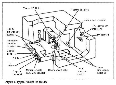
The control console and printer etc. are all located outside the heavily shielded treatment room. Thus, when pressing the key to begin the treatment, the operator does not have any direct access to the machine or the patient. All the occurrences in the treatment room must be observed through the TV monitor and the intercom. The intercom works both ways, that is, the patient can hear the operator (if the operator presses a switch) and the operator can hear the patient. The patient, however, cannot see anything outside the treatment room, while the operator can look in using the TV monitor.
Switching Between Modes: The TurntableTherac-25 is a dual mode machine. This means that it can treat the patient with relativelylow energy electron beams or with X-ray beams. In addition, Therac-25 had a "field light" position that allowed a standard light beam to shine in the path of treatment to help the operator in setting up the machine. Thus there were three modes in which the Therac-25 could operate: electron beam and X-ray for treatment, and field light for setup.
Even though they are relatively low energy, the electron beams are too powerful in their raw form to treat the patient. They need to be spread thinly enough to be the right level of energy. To do this, Therac-25 placed what are called scanning magnets in the way of the beam. The spread of the beam (and also it power) could be controlled by the magnetic fields generated by these magnets. Thus for electron beam therapy, the scanning magnets needed to be placed in the path of the beam.
X-ray treatment requires a very high intensity electron beam (25 MeV) to strike a metal foil. The foil then emits X-rays (photons). This X-ray beam is then "flattened" by a device below the foil, and the X-ray beam of an appropriate intensity is then directed to the patient. Thus, X-ray therapy requires the foil and the flattener to be placed in the path of the electron beam.
The final mode of operation for Therac-25 is not a treatment mode at all. It is merely a light that illuminates the field on the surface of the patient’s body that will be treated with one of the treatment beams. This "field light" required placing a mirror in place to guide the light in a path approximating the treatment beam’s path. This allowed accurate setup of the machine before treatment. Thus, for field light setup, the mirror needed to be placed in the path where one of the treatment beams would eventually go.
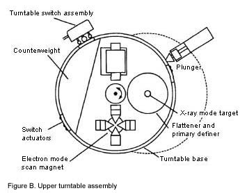
In order to get each of these three assemblies (scanning magnets or X-ray target or field light mirror) in the right place at the right time, the Therac-25 designer placed them on a
turntable. As the name suggests, this is a rotating assembly that has the items for each mode placed on it. The turntable is rotated to the correct position before the beam is started up. This is a crucial piece of the Therac-25 machine, since incorrect matching of the turntable and the mode of operation (e.g. scanning magnets in place but Electron beam turned on high for X-ray) could produce potentially fatal levels of radiation.
Setup and ActuationThe Therac-25 operator sets up the patient on the table using the field light to target the beam. In doing this, treatment parameters must be entered into the machine directly in the treatment room.
He or she then leaves the room and uses the computer console to confirm the treatment parameters (electron or X-ray mode, intensity, duration, etc.). The parameters initially entered in the treatment room appear on the console and the operator simply presses return to confirm each one.
The computer then makes the appropriate adjustments in the machine (moving the turntable, setting the scanning magnets, setting beam intensity etc.). This takes several seconds to do. If the operator notices an error in the input parameters, he or she can, during the setup, edit the parameters at the console without having to start all over again from inside the treatment room.
When the computer indicates that the setup has been done correctly, the operator presses the actuation switch. The computer turns the beam on and the treatment begins. There are three possible outcomes at this point, and they all depend on sensors on the machine. If the sensors indicate no trouble, the treatment concludes successfully. If the sensors indicate a minor problem, like the beam being slightly out of tune, the computer turns the beam off immediately. The operator can then press a "proceed" key to retry the treatment up to 5 times. If the sensors indicate a more serious malfunction, like the beam being significantly stronger or weaker, the computer turns the beam off immediately and requires the machine to be completely setup from the beginning.
The Therac-25's ancestors, Therac-20 and Therac-6, had used a minicomputer (a DEC PDP-11) to add some convenience to the standard hardware of a medical linear accelerator. They both could work without computer control. AECL determined to make its new model, Therac-25, a tightly-coupled combination of software and hardware. Therac-25 software was not written from scratch, but was built up from components that were borrowed from the earlier versions of Therac.
The Machine in the RoomTherac-25 is not just a machine, but an installation consisting of the machine, the PDP-11 that controlled the machine, the shielded room the machine sits in, and the monitoring and control station.
The control console and printer etc. are all located outside the heavily shielded treatment room. Thus, when pressing the key to begin the treatment, the operator does not have any direct access to the machine or the patient. All the occurrences in the treatment room must be observed through the TV monitor and the intercom. The intercom works both ways, that is, the patient can hear the operator (if the operator presses a switch) and the operator can hear the patient. The patient, however, cannot see anything outside the treatment room, while the operator can look in using the TV monitor.
Switching Between Modes: The TurntableTherac-25 is a dual mode machine. This means that it can treat the patient with relativelylow energy electron beams or with X-ray beams. In addition, Therac-25 had a "field light" position that allowed a standard light beam to shine in the path of treatment to help the operator in setting up the machine. Thus there were three modes in which the Therac-25 could operate: electron beam and X-ray for treatment, and field light for setup.
Even though they are relatively low energy, the electron beams are too powerful in their raw form to treat the patient. They need to be spread thinly enough to be the right level of energy. To do this, Therac-25 placed what are called scanning magnets in the way of the beam. The spread of the beam (and also it power) could be controlled by the magnetic fields generated by these magnets. Thus for electron beam therapy, the scanning magnets needed to be placed in the path of the beam.
X-ray treatment requires a very high intensity electron beam (25 MeV) to strike a metal foil. The foil then emits X-rays (photons). This X-ray beam is then "flattened" by a device below the foil, and the X-ray beam of an appropriate intensity is then directed to the patient. Thus, X-ray therapy requires the foil and the flattener to be placed in the path of the electron beam.
The final mode of operation for Therac-25 is not a treatment mode at all. It is merely a light that illuminates the field on the surface of the patient’s body that will be treated with one of the treatment beams. This "field light" required placing a mirror in place to guide the light in a path approximating the treatment beam’s path. This allowed accurate setup of the machine before treatment. Thus, for field light setup, the mirror needed to be placed in the path where one of the treatment beams would eventually go.
In order to get each of these three assemblies (scanning magnets or X-ray target or field light mirror) in the right place at the right time, the Therac-25 designer placed them on a
turntable. As the name suggests, this is a rotating assembly that has the items for each mode placed on it. The turntable is rotated to the correct position before the beam is started up. This is a crucial piece of the Therac-25 machine, since incorrect matching of the turntable and the mode of operation (e.g. scanning magnets in place but Electron beam turned on high for X-ray) could produce potentially fatal levels of radiation.
Setup and ActuationThe Therac-25 operator sets up the patient on the table using the field light to target the beam. In doing this, treatment parameters must be entered into the machine directly in the treatment room.
He or she then leaves the room and uses the computer console to confirm the treatment parameters (electron or X-ray mode, intensity, duration, etc.). The parameters initially entered in the treatment room appear on the console and the operator simply presses return to confirm each one.
The computer then makes the appropriate adjustments in the machine (moving the turntable, setting the scanning magnets, setting beam intensity etc.). This takes several seconds to do. If the operator notices an error in the input parameters, he or she can, during the setup, edit the parameters at the console without having to start all over again from inside the treatment room.
When the computer indicates that the setup has been done correctly, the operator presses the actuation switch. The computer turns the beam on and the treatment begins. There are three possible outcomes at this point, and they all depend on sensors on the machine. If the sensors indicate no trouble, the treatment concludes successfully. If the sensors indicate a minor problem, like the beam being slightly out of tune, the computer turns the beam off immediately. The operator can then press a "proceed" key to retry the treatment up to 5 times. If the sensors indicate a more serious malfunction, like the beam being significantly stronger or weaker, the computer turns the beam off immediately and requires the machine to be completely setup from the beginning.
Subscribe to:
Posts (Atom)