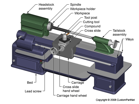
Turning machines, typically referred to as lathes, can be found in a variety of sizes and designs. While most lathes are horizontal turning machines, vertical machines are sometimes used, typically for large diameter workpieces. Turning machines can also be classified by the type of control that is offered. A manual lathe requires the operator to control the motion of the cutting tool during the turning operation. Turning machines are also able to be computer controlled, in which case they are referred to as a computer numerical control (CNC) lathe. CNC lathes rotate the workpiece and move the cutting tool based on commands that are preprogrammed and offer very high precision. In this variety of turning machines, the main components that enable the workpiece to be rotated and the cutting tool to be fed into the workpiece remain the same. These components include the following:
Bed
- The bed of the turning machine is simply a large base that sits on the ground or a table and supports the other components of the machine.Headstock assembly
- The headstock assembly is the front section of the machine that is attached to the bed. This assembly contains the motor and drive system which powers the spindle. The spindle supports and rotates the workpiece, which is secured in a workpiece holder or fixture, such as a chuck or collet.Tailstock assembly
- The tailstock assembly is the rear section of the machine that is attached to the bed. The purpose of this assembly is to support the other end of the workpiece and allow it to rotate, as it's driven by the spindle. For some turning operations, the workpiece is not supported by the tailstock so that material can be removed from the end.Carriage
- The carriage is a platform that slides alongside the workpiece, allowing the cutting tool to cut away material as it moves. The carriage rests on tracks that lay on the bed, called "ways", and is advanced by a lead screw powered by a motor or hand wheel.Cross slide
- The cross slide is attached to the top of the carriage and allows the tool to move towards or away from the workpiece, changing the depth of cut. As with the carriage, the cross slide is powered by a motor or hand wheel.Compound
- The compound is attached on top of the cross slide and supports the cutting tool. The cutting tool is secured in a tool post which is fixed to the compound. The compound can rotate to alter the angle of the cutting tool relative to the workpiece.Turret
- Some machines include a turret, which can hold multiple cutting tools and rotates the required tool into position to cut the workpiece. The turret also moves along the workpiece, feeding the cutting tool into the material. While most cutting tools are stationary in the turret, live tooling can also be used. Live tooling refers to powered tools, such as mills, drills, reamers, and taps, which rotate and cut the workpiece.

No comments:
Post a Comment